
Linear-motion telescopic mechanism and robot arm having linear-motion telescopic mechanism

Active Publication Date: 2012-02-02
NAT INST OF ADVANCED IND SCI & TECH +1
View PDF16 Cites 57 Cited by
  • Summary
  • Abstract
  • Description
  • Claims
  • Application Information

AI Technical Summary

Benefits of technology

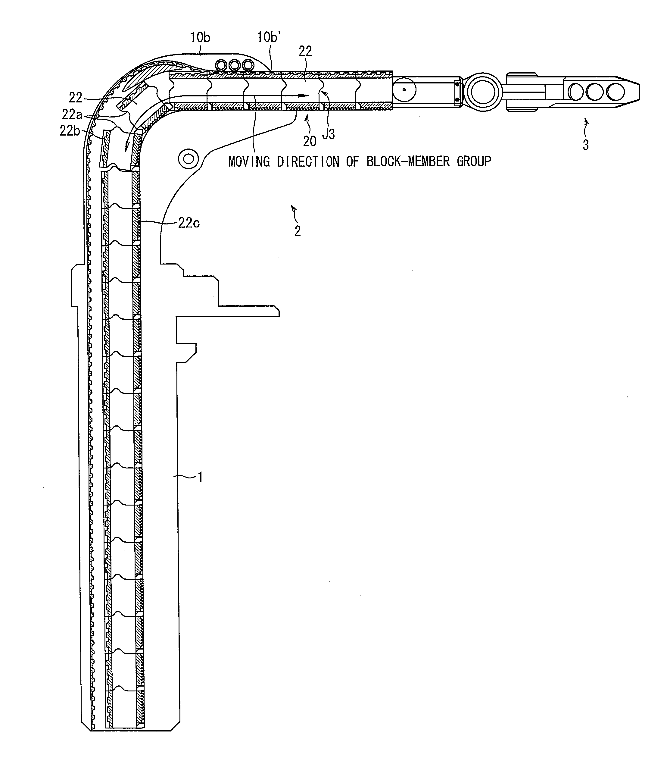
[0022]As described above, in order to achieve the above object, a linear-motion telescopic mechanism according to the present invention includes: a block-member group including a plurality of block members; moving means which moves the plurality of block members and which has a function of fixing a given block member to another block member in the block-member group and of unfixing fixed block members one by one, the moving means causing a part of or all of the plurality of block members in the block-member group to align in a linear and rigid manner to form a rigid alignment, and unfixing a part of or all of the rigid alignment to disengage the block members one by one, so that the rigid alignment serves as a linear rigid arm section that is freely variable in length.
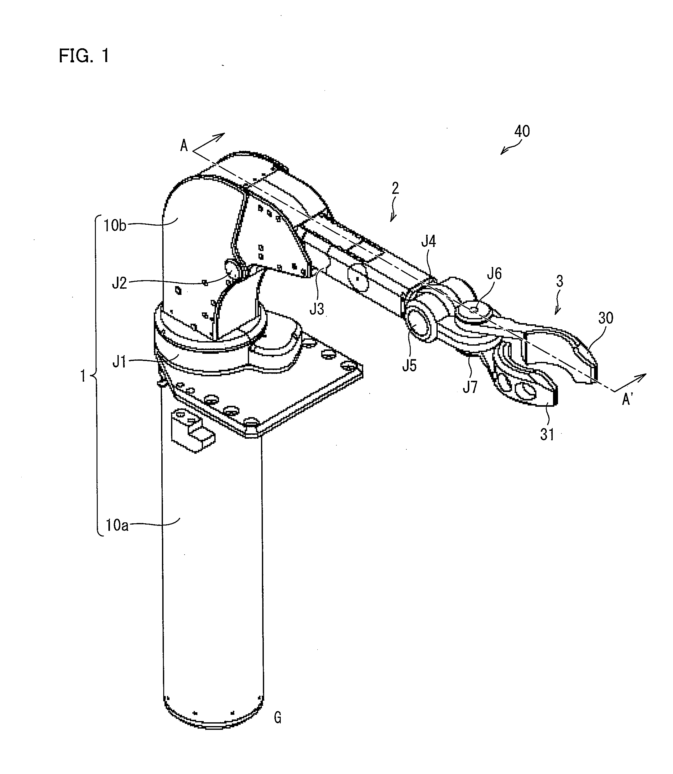
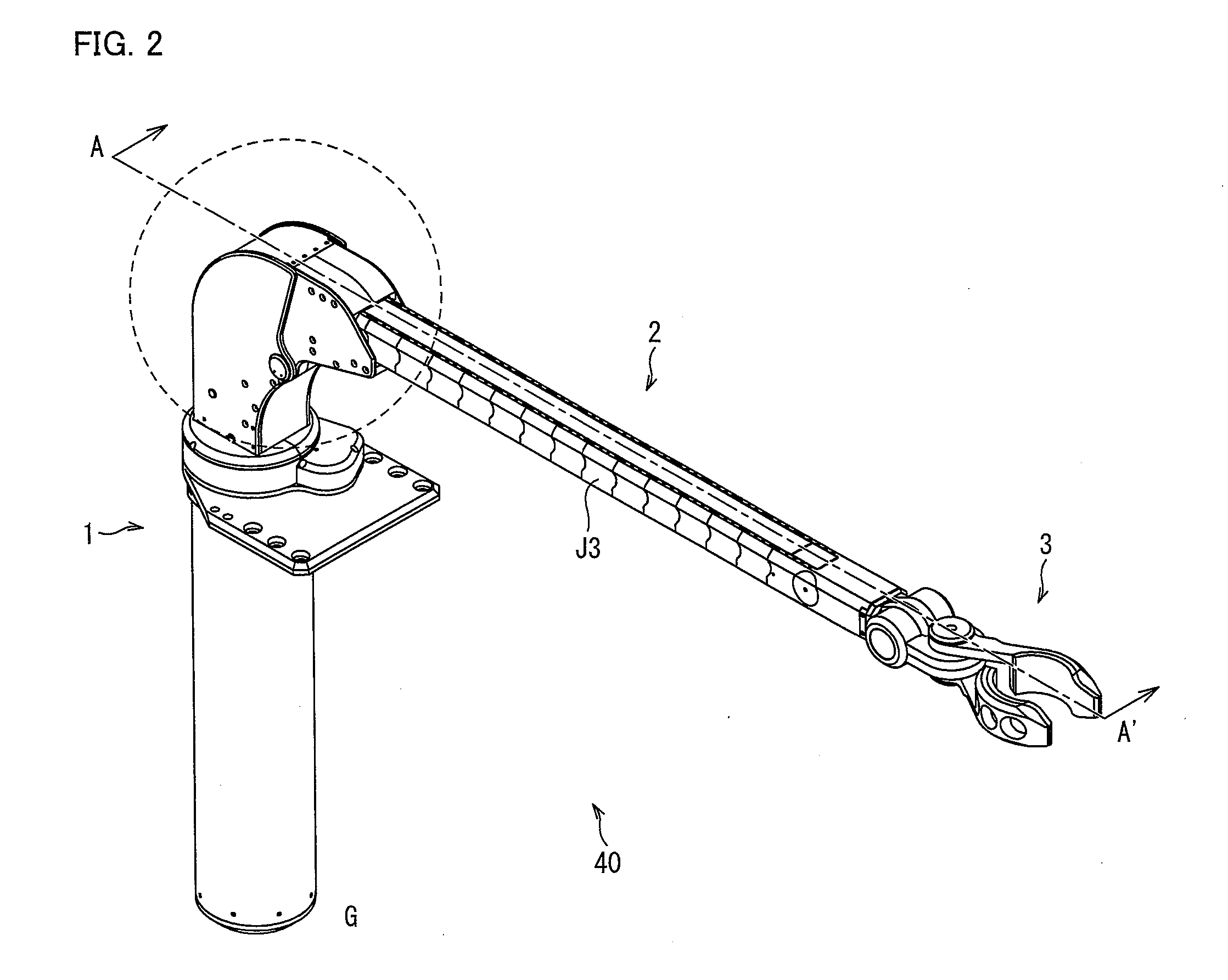
[0023]Further, as described above, in order to achieve the above object, a robot arm according to the present invention includes: an installation section to be fixed to a desk, a floor, or the like; a support member connected to the installation section via a rotatable first rotational joint; a straight-link arm section connected to the support member via a second rotational joint that is rotatable in a vertical direction to the first rotational joint; and an end effector provided at an end of the arm section, the arm section having a linear-motion telescopic mechanism, (i) which allows the arm section to be elongated or contracted to an arbitrary arm length and (ii) which is constituted by structural members provided in advance to achieve a maximum arm length, the linear-motion telescopic mechanism being arranged to separate, from the arm section, a part of the structural members that is beyond the arbitrary arm length and to house the part into a space deviating from a central axis of the arm section along an elongate direction of the arm section.
[0024]With the above arrangement, it is possible to provide a linear-motion telescopic mechanism and a robot arm, each of which significantly reduce an occurrence of a conventional problem, i.e., the risk that an object is caught between sections of the robot arm, and each of which has a reduced space to be occupied by the robot arm.

Problems solved by technology

This increases such a risk that a projected portion strikes or hits an object around the robot arm.
Further, there is a risk that an object around the robot arm may be caught between the arm sections 102.
In view of this, it can be said that this robot arm is not suitable especially as an assistive robot arm used in daily life.
However, in these three types of arrangements of (b) to (d) of FIG. 28, in order to achieve sufficient stiffness, it is necessary to design the real mechanisms thick in a contraction state, thereby resulting in that the appearances of these mechanisms look quite unlike the appearance of the ideal arm section illustrated in (a) of FIG. 28.
As a result, a volume, i.e., a product of the thickness and the length, of an arm structure for an unnecessary portion in the contraction state (hereinafter referred to as an unnecessary portion of the arm section) gets quite bulky, and a volume necessary to house the unnecessary portion makes the base portion and its auxiliary mechanism larger.
However, these robot arms are not produced from the viewpoint of avoiding the aforementioned risk of getting caught between arm sections or for the purpose of being used beside people.
However, the two-legged robot is a very ambitious device, and therefore unsuitable for a robot arm, which requires weight saving.

Method used


Image

  • Linear-motion telescopic mechanism and robot arm having linear-motion telescopic mechanism
  • Linear-motion telescopic mechanism and robot arm having linear-motion telescopic mechanism
  • Linear-motion telescopic mechanism and robot arm having linear-motion telescopic mechanism

Examples


embodiment 1

[0055]A linear-motion telescopic mechanism according to the present invention includes a block-member group constituted by a plurality of block members, and moving means which moves the plurality of block members and which has a function of fixing a given block member to another block member in the block-member group and for unfixing fixed block members one by one. In the linear-motion telescopic mechanism, the moving means causes a part of or all of the plurality of block members in the block-member group to align in a linear and rigid manner to form a rigid alignment, and unfixes a part of or all of the rigid alignment to disengage the block members one by one, so that the rigid alignment serves as a linear rigid arm section that is freely variable in length.

[0056]The following describes the linear-motion telescopic mechanism according to the present invention more specifically, by referring to a robot arm as one embodiment, based on FIG. 1 to FIG. 15. For convenience for explanat...

embodiment 2

[0096]A robot arm of the present invention includes: an installation section to be fixed on a desk, a floor, or the like; a support member connected to the installation section via a rotatable first rotational joint; a straight-link arm section connected to the support member via a second rotational joint, which is rotatable in a vertical direction to a rotational direction of the first rotational joint; and an end effector provided at an end of the arm section, and the arm section having a linear-motion telescopic mechanism, (i) which allows the arm section to be elongated or contracted to an arbitrary arm length and (ii) which is constituted by structural members provided in advance to achieve a maximum arm length, the linear-motion telescopic mechanism being arranged to separate, from the arm section, a part of the structural members that is beyond the arbitrary arm length and to house the part into a space deviating from a central axis of the arm section along an elongate direct...


PUM


Abstract

A linear-motion telescopic mechanism according to the present invention includes a plurality of block members (22) by which an arbitrary arm length is achieved in such a manner that the plurality of block member (22) are rigidly connected to each other so as to elongate a linear-motion telescopic joint (J3). On the other hand, by separating the plurality of block members (22) one by one from a rigid alignment of the plurality of block members (22), the linear-motion telescopic joint (J3) is contracted. The block members (22) unfixed from the rigid alignment are still serially connected but not in a rigid manner. That is, the block members (22) thus unfixed can be flexed in any directions, and therefore can be housed inside a support member (1) in a compact manner. This arrangement can provide a linear-motion telescopic mechanism (i) which enhances safety by eliminating such a risk, inevitable for a typical robot arm having an elbow joint, that an object around the robot arm gets caught between arm sections when the elbow joint is closed, and (ii) which can reduce a space to be occupied by the robot arm.

Description

TECHNICAL FIELD[0001]The present invention relates to a linear-motion telescopic mechanism. More specifically, the present invention relates to (i) a linear-motion telescopic mechanism which enhances safety by eliminating such a risk inevitable for a typical robot arm having an elbow joint that an object placed in vicinity to the robot arm is caught between sections of the robot arm when the elbow joint is closed, and which has a reduced space to be occupied by the robot arm, and (ii) a robot arm having the linear-motion telescopic mechanism.BACKGROUND ART[0002]In recent years, robot arms are being used cooperatively with people among production facilities, and also used for assistive aids in daily life to maintain or improve the quality of life of elderly people and people with disabilities.[0003]One typical example of the robot arms is a robot arm having an arrangement as illustrated in (a) and (b) of FIG. 27. That is, the robot arm includes a base portion 100, an end effector 101...

Claims


Application Information

Patent Timeline
IPC IPC(8): F16H19/02B25J18/06
CPCB25J9/045B25J9/046B25J18/025B25J18/06Y10T74/20329F16H19/0636F16H25/2409Y10T74/18152F16G13/20
Inventor KAWABUCHI, ICHIROYOON, WOO-KEUNKOTOKU, TETSUO
Owner NAT INST OF ADVANCED IND SCI & TECH
Learn More