Agricultural sizer with item stabilizer belt

a technology of item stabilizer and sizer, applied in the field of agricultural sizer, can solve the problems of item loss, loss of desired sequential, lineal arrangement, etc., and achieve the effect of suppressing undesirable action and movement and effective sorting action

Active Publication Date: 2018-02-01
MILLS DANIEL G
View PDF17 Cites 10 Cited by
  • Summary
  • Abstract
  • Description
  • Claims
  • Application Information

AI Technical Summary

Benefits of technology

[0017]An upper stabilizer belt is further provided, to maintain the items in a secure relation on the lower conveyor belt, particularly as each item passes through the sampling window. The upper stabilizer belt is arranged above and generally in alignment with the lower conveyor belt. The upper stabilizer belt is flexible and is driven at a speed to match the speed of the lower conveyor belt, so they will move in unison.
[0018]The upper stabilizer belt is suspended at both ends in such a manner as to engage the items incoming from the upstream singulator. The if items are bouncing or moving about as they are about to enter the sizing apparatus, the upper stabilizer belt suppresses this undesirable action and movement. The upper stabilizer belt further maintains loose contact with the items, until they have at least passed through the sampling window. This dampening effect ensures that the images of the items obtained by the sampling means, will be sharp and accurate. Accurate image data for an item, in turn, ensures that the determinations made about that item will also be accurate, and that the effectiveness of sorting actions based on those determinations will be improved.

Problems solved by technology

If the speed is too slow, incoming items may collect and bunch at the input end, causing the items to lose their sequential, lineal arrangement.
If the speed is too fast, the items may roll and bounce on the lower conveyor belt, again causing loss of the desired sequential, lineal arrangement.

Method used


Image

  • Agricultural sizer with item stabilizer belt
  • Agricultural sizer with item stabilizer belt
  • Agricultural sizer with item stabilizer belt

Examples


Embodiment Construction

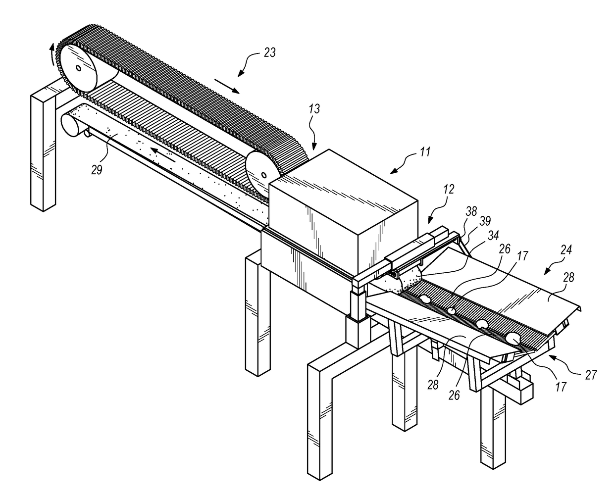
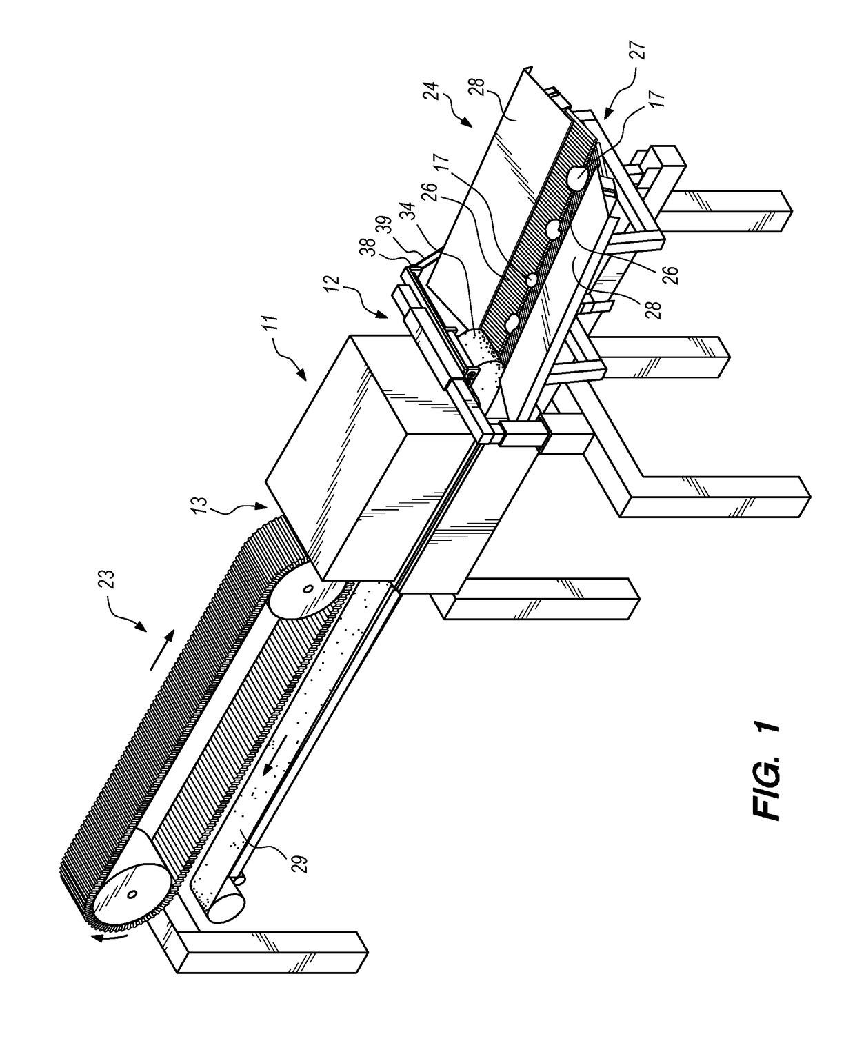
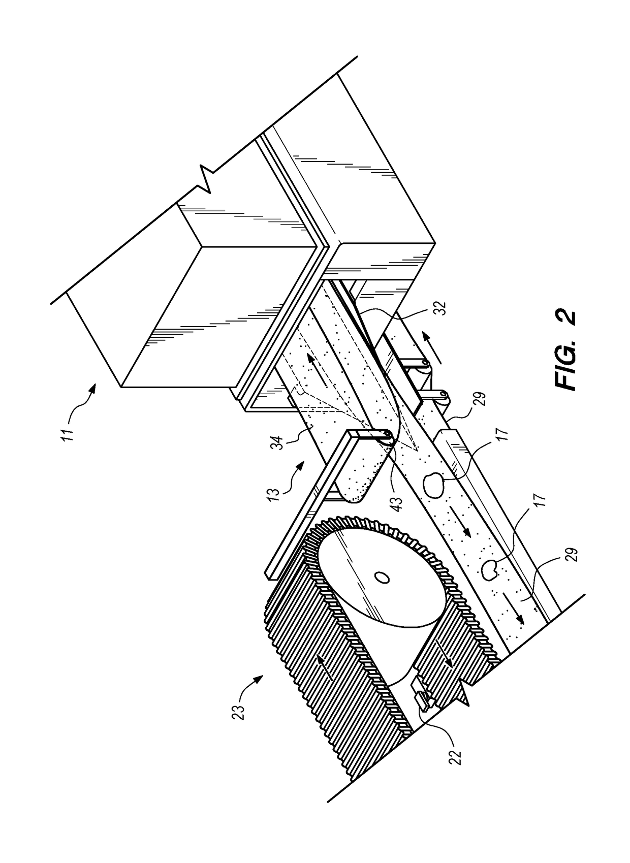
[0026]Turning now to FIGS. 1 and 4, the sizing apparatus 11 has an input end 12, an output end 13, and a sampling window 14 therebetween. The sizing apparatus 11 includes sizing means 16, shown in FIG. 5, for determining at least the size of each item 17 passing through the sampling window 14. Preferably, the sizing means 16 comprises an X-Ray source 18 and a plurality of detectors 19, along with a computer 21 and associated software for analyzing the data provided by the sampling process for each item 17.

[0027]The X-Ray source 18 is a low powered X-Ray generator, which produces synchronous pulses of energy in concert with control signals from computer 21. The Spellman company of Hauppauge, N.Y., manufactures suitable X-Ray sources for this application. The plurality of detectors 19 is oriented transversely, with respect to the direction of travel of each item 17. In that manner, successive “slices” of the item 17 are exposed and detected, and item image data is outputted to compute...


PUM

PropertyMeasurementUnit
sizeaaaaaaaaaa
speedaaaaaaaaaa
flexibleaaaaaaaaaa

Abstract

A sizing apparatus has input and output ends and a sampling window therebetween. Sizing means determines the size of each item passing through the sampling window. Singulating means arranges the items in a line and delivers them sequentially at the input end of the sizing apparatus. A lower conveyor belt extends through the sizing apparatus from the input end through the sampling window to the output end. The lower conveyor belt is translated at a speed sufficient to receive, transport, and maintain the items in sequential fashion. A flexible upper stabilizer belt is arranged above and generally in alignment with the lower conveyor belt, and is driven to match the speed of the lower conveyor belt. The upper stabilizer belt is suspended so as to engage the items incoming from said singulating means and to maintain loose contact with them until the items have passed through the sampling window.

Description

BACKGROUND OF THE INVENTION1. Field of the Invention[0001]The invention relates generally to apparatus for accurately determining the size of agricultural comestibles and performing sorting operations based upon those determinations. More specifically, the invention pertains to an agricultural sizer provided with an improved apparatus for stabilizing food items during the period when they are sampled by X-Ray irradiation, for size and other characteristics.2. Description of the Prior Art[0002]U.S. Pat. No. 5,847,382 issued to Koch et al., discloses a Bone Detector. This device includes a flexible clear plastic lower conveyor to transport deboned poultry. A fluorescent bulb illuminates the passing food product from below. An upper conveyor belt has a portion which runs parallel to and in spaced relation from the lower conveyor. The upper conveyor is made from a plurality of linked rigid plastic slats which bear down on the poultry to reduce its thickness during the bone detection pro...

Claims


Application Information

Patent Timeline
Patent Type & Authority Applications(United States)
IPC IPC(8): G01N23/02G01N33/10G01N33/02B07C1/04B07C5/04
CPCG01N23/02B07C1/04B07C5/04B65G15/14G01N33/10B07C2501/0081G01N33/025B07C5/02G01N23/087G01N2223/618G01N2223/643G01N2223/6466
Inventor MILLS, DANIEL G.
Owner MILLS DANIEL G
Why Eureka
Try Eureka