

Liquid discharging device
- Summary
- Abstract
- Description
- Claims
- Application Information
AI Technical Summary
Benefits of technology
Problems solved by technology
Method used
Image

Examples
first embodiment
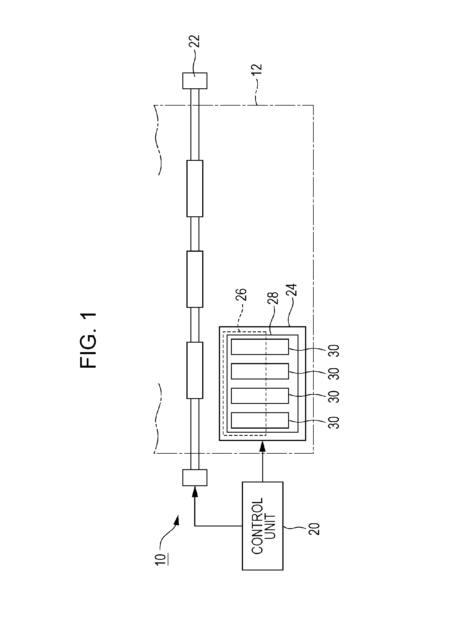
[0027]FIG. 1 is a configuration diagram of a liquid discharging device 10 according to a first embodiment of the invention. The liquid discharging device 10 of the first embodiment is an ink jet printing device that discharges ink that is an example of liquid on a medium 12 such as printing paper and the like. As illustrated in FIG. 1, the liquid discharging device 10 includes a control unit 20, a transport mechanism 22, a carriage 24, a liquid discharging portion 26, and a container mounting portion 28. The control unit 20 integrally controls each portion of the liquid discharging device 10. The transport mechanism 22 transports the medium 12 in a predetermined direction under the control of the control unit 20.
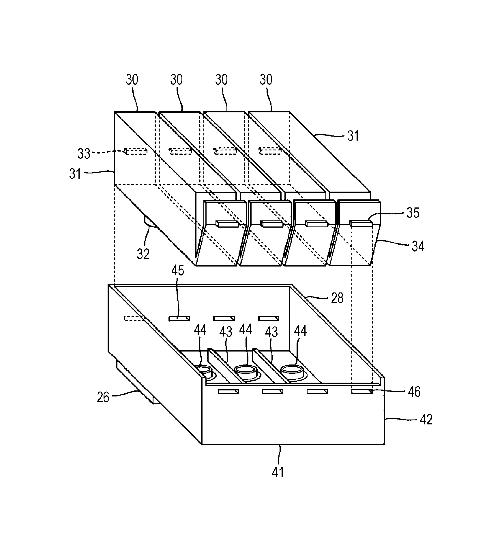
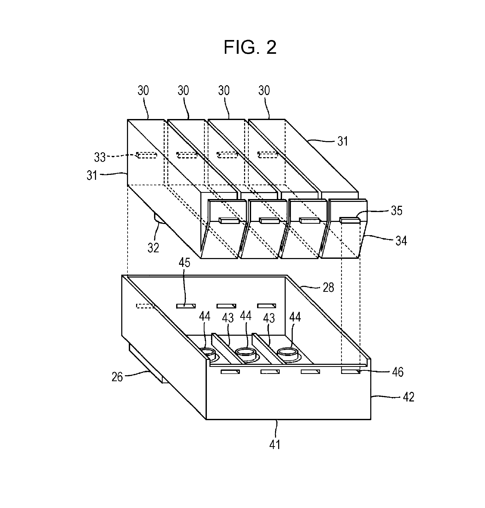
[0028]The liquid discharging portion 26 and the container mounting portion 28 are mounted on the carriage 24 of the first embodiment and a plurality of the liquid containers (cartridge) 30 for storing a plurality of types of ink that are different from each other are detacha...
second embodiment
[0046]A second embodiment of the invention will be described. A detailed description with respect to elements having the same effects or functions in each embodiment exemplified below as that of the first embodiment will be appropriately omitted by using numerals used in the description of the first embodiment.
[0047]FIG. 6 is a plan view and a sectional view of the connection portion 44 in the second embodiment. In the first embodiment, the holding portion 53A of an annular shape protruded from an outer peripheral surface over the entire circumference of the second portion 52 is exemplified. As illustrated in FIG. 6, in the connection portion 44 of the second embodiment, a plurality of holding portions 53B are installed at positions different from the circumferential direction of the second portion 52. Each of the plurality of the holding portions 53B is a portion upwardly projected on the contact surface SB of the sealing body 48, by being formed on an outer peripheral surface of t...
third embodiment
[0050]FIG. 8 is a plan view and a sectional view in the vicinity of one connection portion 44 in a third embodiment. As illustrated in FIG. 8, in the third embodiment, a plurality of protruding portions 62 are used to hold the sealing body 48. The plurality of protruding portions 62 are a structural body of a pin shape protruded appropriately perpendicular to the base surface SA of the container mounting portion 28. On the other hand, an insertion hole 482 to which each of the protruding portions 62 is inserted is formed in the sealing body 48. The sealing body 48 is held by a holding portion 53C deformed from a tip end portion projected from the contact surface SB among the protruding portions 62 inserted to the insertion hole 482 of the sealing body 48. The holding portion 53C of the third embodiment is an eaves shape portion upwardly projected on the contact surface SB of the sealing body 48. Similar to the holding portion 53A of the first embodiment and the holding portion 53B o...
PUM
 Abstract
Description
Claims
Application Information