Transmission apparatus, transmission method, reception apparatus, and reception method

a technology of transmission apparatus and reception apparatus, which is applied in the direction of data switching network, selective content distribution, synchronisation arrangement, etc., can solve the problem of presentation control problems such as the one-time leap second that occurs in several years, and achieve the effect of suppressing the influence of the reception side by occurrence of a leap second

Active Publication Date: 2018-02-01
SONY CORP
View PDF1 Cites 10 Cited by
  • Summary
  • Abstract
  • Description
  • Claims
  • Application Information

AI Technical Summary

Benefits of technology

[0040]According to the present technology, influence on a reception side by occurrence of a leap second can be suppressed. Note that effects described herein are merely examples and thus are not limited thereto. Additional effects may also be included.

Problems solved by technology

In a case where absolute time (UTC) is employed as a reference time axis for presentation synchronization, a leap second that occurs once in several years is a problem in presentation control.

Method used


Image

  • Transmission apparatus, transmission method, reception apparatus, and reception method
  • Transmission apparatus, transmission method, reception apparatus, and reception method
  • Transmission apparatus, transmission method, reception apparatus, and reception method

Examples


first embodiment

1. First Embodiment

[0077][Exemplary Configuration of Transmission / Reception System]

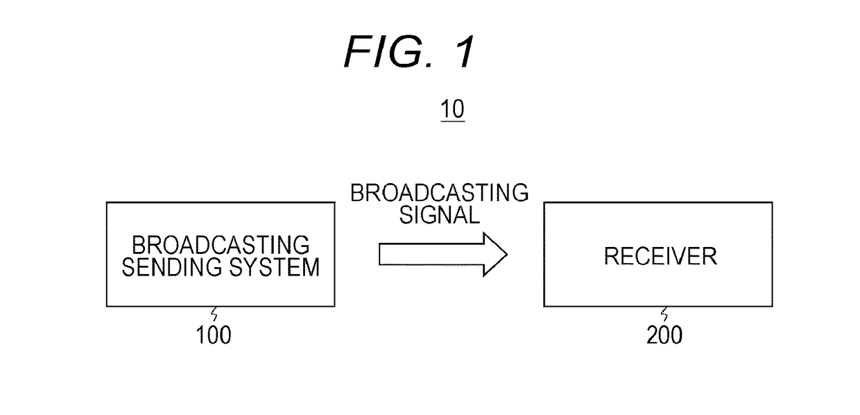
[0078]FIG. 1 illustrates an exemplary configuration of a transmission / reception system 10 as a first embodiment. The transmission / reception system 10 includes a broadcasting sending system 100 and a receiver 200.

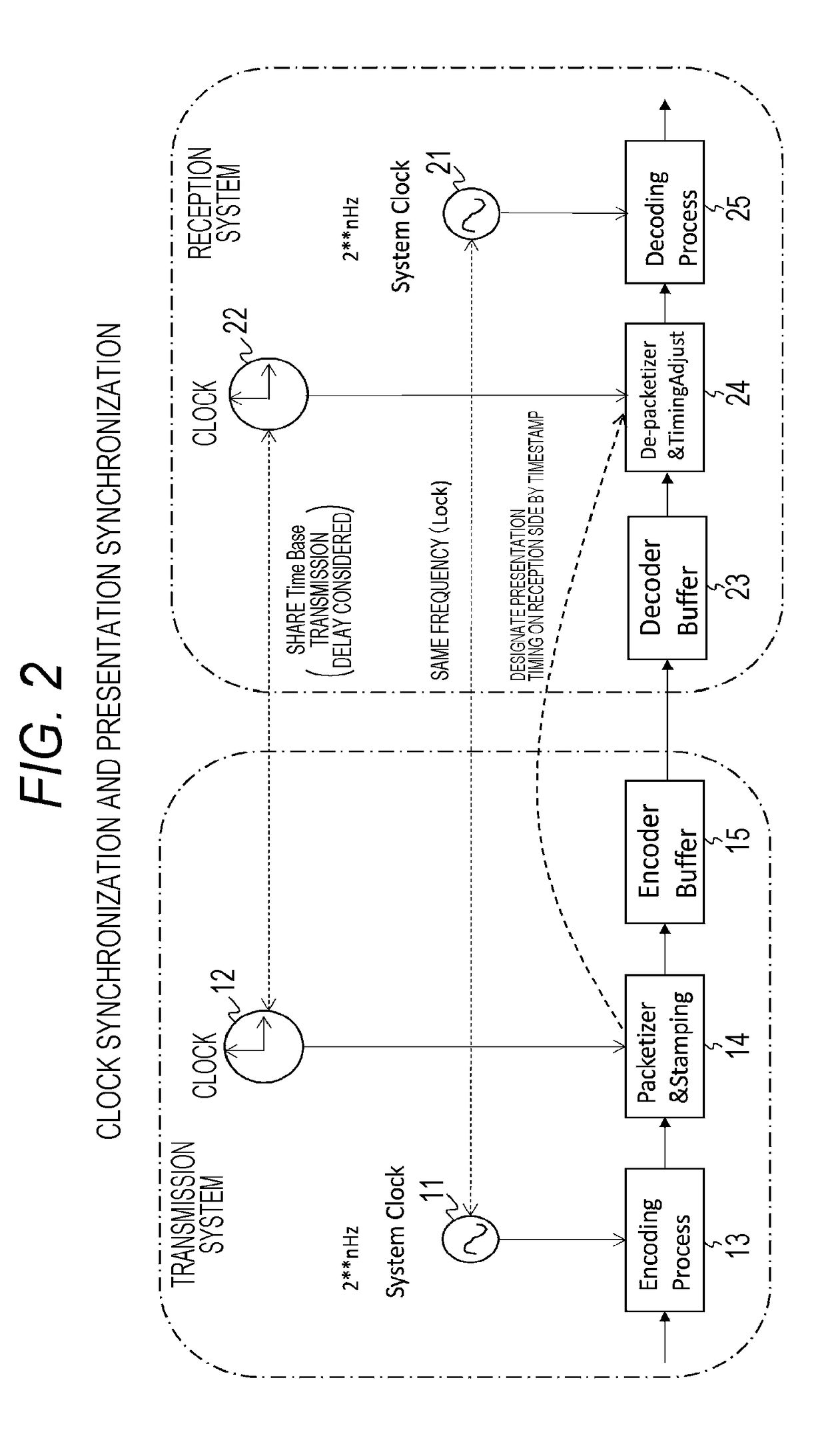
[0079]The broadcasting sending system 100 transmits a broadcasting signal of the Internet Protocol (IP) system including transmission media such as video and audio. The broadcasting sending system 100 acquires absolute time information from an external source. For example, it is acquired in a Network Time Protocol (NTP) long format from an NTP server by the NTP or from another device by the IEEE1588PTP.

[0080]The broadcasting sending system 100 generates absolute time information synchronized with the absolute time information acquired from the external source. A broadcasting signal includes transmission media as well as the generated absolute time information and presentation time of each pres...

second embodiment

2. Second Embodiment

[0233][Exemplary Configuration of Transmission / Reception System]

[0234]FIG. 31 illustrates an exemplary configuration of a transmission / reception system 10A as a second embodiment. The transmission / reception system 10A is a system of a multistream service (broadcast and communication cooperation) and includes broadcasting sending systems 100A and 100B, a distribution device 100C, and a receiver 200A.

[0235]Broadcasting sending systems 100A and 100B transmit a broadcasting signal of the Internet Protocol (IP) system including transmission media such as video and audio. The broadcasting sending system 100A has a clock unit (time information generating unit) 151A which generates absolute time information on the basis of absolute time information acquired from an external source, a video / audio encoder 152A which performs encoding processing on transmission media such as video and audio, and a sending device 153A which transmits the absolute time information (NTP data) ...


PUM


Abstract

A time information generating unit generates absolute time information synchronized with absolute time information acquired from an external source. The time information generating unit generates time information by shifting, to shifted time, occurrence time of a leap second that can be represented by the absolute time information acquired from the external source. A transmission unit transmits a signal including transmission media and the absolute time information generated by the time information generating unit. Thereby, influence on a reception side by occurrence of a leap second is suppressed.

Description

TECHNICAL FIELD[0001]The present technology relates to a transmission apparatus, a transmission method, a reception apparatus, and a reception method and especially to a transmission apparatus for transmitting a signal of the IP system including transmission media such as video and audio, a transmission method, a reception apparatus, and a reception method.BACKGROUND ART[0002]As a next-generation broadcasting system, transmission systems for transmitting by a content format based on MP4 ISO base media file format based on IP protocols, such as MMT, are under review (e.g. see Non Patent Document 1). In a case where absolute time (UTC) is employed as a reference time axis for presentation synchronization, a leap second that occurs once in several years is a problem in presentation control.CITATION LISTNon Patent Document[0003]Non Patent Document 1: Study of ISO / IEC CD 23008-1 MPEG Media Transport, [online], retrieved on May 7, 2013, the Internet<URL: http: / / mpeg.chiariglione.org / st...

Claims


Application Information

Patent Timeline
Patent Type & Authority Applications(United States)
IPC IPC(8): H04J3/06H04L12/18H04W56/00
CPCH04J3/0667H04W56/0015H04L12/1881H04H60/40H04N21/4302H04J3/0664H04N21/8547H04N21/845
Inventor KITAZATO, NAOHISA
Owner SONY CORP
Why Eureka
Try Eureka