
An illumination device for illuminating close objects and method thereof

Inactive Publication Date: 2018-02-08
FORUS HEALTH PVT
View PDF1 Cites 3 Cited by
  • Summary
  • Abstract
  • Description
  • Claims
  • Application Information

AI Technical Summary

Benefits of technology

The present disclosure relates to an illumination device which uses a collar to guide light from one or more sources towards an object for close examination. The collar utilizes the principle of Total Internal Reflection (TIR) to efficiently direct the light. This device provides an improved method for illuminating a target area and offers advantage over previous methods.

Problems solved by technology

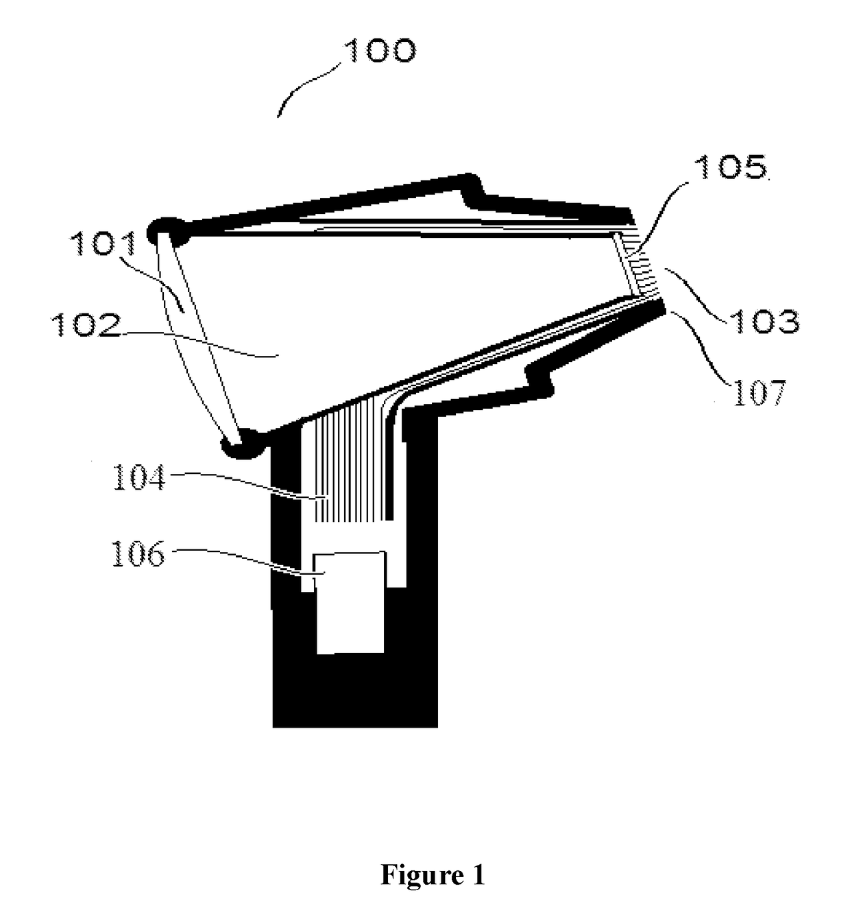
However, with most source types it is impractical to create bright light at the point where the light emerges.
The principal reasons are well illustrated by the incandescent bulb, which is hard to miniaturize and very fragile when small, and by the nature of incandescence (light emission at high temperature) also yields heat, which can be painful or dangerous.
High curvature leads to stress on the fibers, and leakage of light.
This is a significant element in manufacturing cost.
However, on the scale of the tips 103, individual rays are a poor approximation to optics.
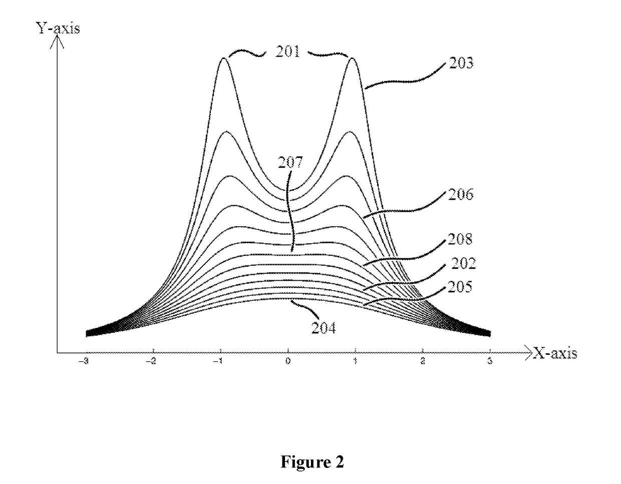
In the case of an ophthalmoscope or fundus camera, illumination through the cornea and lens of the eye changes the pattern, but the effect at the distance of the retina remains unadjustable: brightest in the central part of the image.
Non-uniform lighting makes it harder to distinguish clinically important features.

Method used


Image

  • An illumination device for illuminating close objects and method thereof
  • An illumination device for illuminating close objects and method thereof
  • An illumination device for illuminating close objects and method thereof

Examples


Embodiment Construction

[0023]The foregoing_has broadly outlined the features and technical advantages of the present disclosure in order that the detailed description of the disclosure that follows may be better understood. Additional features and advantages of the disclosure will be described hereinafter, which form the subject of the claims of the disclosure. It should be appreciated by those skilled in the art that the conception and specific aspect disclosed may be readily utilized as a basis for modifying or designing other structures for carrying out the same purposes of the present disclosure.

[0024]In the present document, the word “exemplary” is used herein to mean “serving as an example, instance, or illustration.” Any embodiment or implementation of the present subject matter described herein as “exemplary” is not necessarily to be construed as preferred or advantageous over other embodiments.

[0025]While the disclosure is susceptible to various modifications and alternative forms, a specific emb...


PUM


Abstract

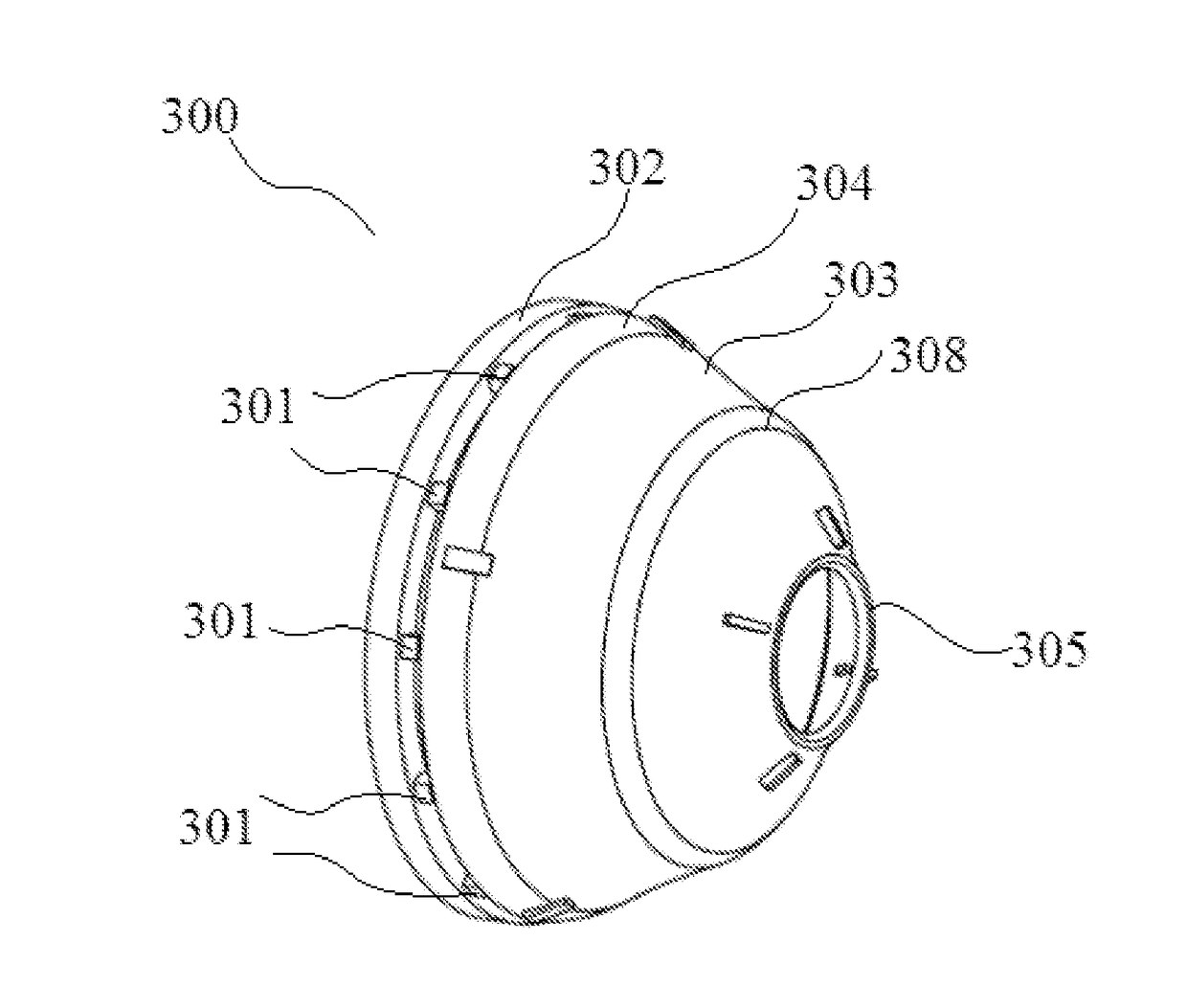
Embodiments of the present disclosure provides an illumination device (300), comprises of one or more sources (301) which provides light arranged in a predefined configuration and a collar (303) with a first end (304) and a second end (305) to guide light received at the first end towards the second end. The collar guides the light in a medium between an internal wall and an external wall of the collar by reflection. The light from the second end is used to illuminate a target area for an imaging device. The method of illuminating a target area by an illumination device comprises of powering one or more sources to provide light for illumination and guiding the light in the medium to illuminate on the target area.

Description

TECHNICAL FIELD[0001]The present disclosure relates to an illumination device. More particularly, the disclosure relates to an illumination device for illuminating a close object for performing an examination.BACKGROUND[0002]It is often necessary, in using an optical device for close examination of an object, to shine strong light onto the object or for interior examination into the object. Typical optical devices are otoscopes, ophthalmoscopes, and endoscopes of many types according to the part of the body where the optical devices are inserted. A similar need for especially directed light occurs with microscopes, but since the apparatus typically surrounds the sample there are more options in providing that light, including trans-illumination from behind the sample. In examining an intact structure, and especially an interior one, with a single maneuverable device, the illumination must usually emerge from the device structure, near to the optical pathway along which light returns...

Claims


Application Information

Patent Timeline
IPC IPC(8): A61B1/06A61B1/07A61B1/227A61B1/00
CPCA61B1/0607A61B1/0019A61B1/0684A61B1/07A61B1/227A61B1/0676A61B1/00096A61B1/042A61B3/0008A61B3/107
Inventor KUMAR, COTHURU SANTOSHRAO, SHYAM VASUDEVAPOSTON, TIMOTHYVINEKAR, ANAND S.
Owner FORUS HEALTH PVT
Features
  • Generate Ideas
  • Intellectual Property
  • Life Sciences
  • Materials
  • Tech Scout
  • Unparalleled Data Quality
  • Higher Quality Content
  • 60% Fewer Hallucinations
Learn More