Eureka AIR delivers breakthrough ideas for toughest innovation challenges, trusted by R&D personnel around the world.

Dual cyclone separator

Inactive Publication Date: 2018-02-08
JCI CYCLONIC TECH LTD
View PDF44 Cites 4 Cited by
  • Summary
  • Abstract
  • Description
  • Claims
  • Application Information

AI Technical Summary

Benefits of technology

The present invention is a cylonic separator system for separating mixed heavy phase / light phase process streams. It consists of at least two cyclonic chambers with a common tangential inlet, gas outlet, and outer shell. The process stream enters through the inlet and swirls around the inner surface of each chamber to separate the heavy and light phases. The heavy phase exits through the lower end of the chambers while the light phase rises through the central axis and exits through the gas outlet on the upper end of the chambers. The invention has a simple design and can effectively separate process streams, making it useful in various industrial applications.

Problems solved by technology

There are further limits to the design of the tangential inlets to each of the cyclonic chambers to create the desired high momentum and flow rate of the incoming process fluid.
Typically, when using multiple separators, these specific size requirements lead to a height and diameter that is often too narrow and tall to withstand the high vibration commonly experienced in the separation environment.
Limitations to sump size lead to less than desirable residence time to separate out any entrained gases that may be trapped in the falling liquid.
Involute or tangential inlets commonly used on cyclonic separators connect with the separator body in such a way that can prove difficult to meet the reinforcement requirements that are needed for the design of a pressure vessel.

Method used


Image

  • Dual cyclone separator
  • Dual cyclone separator
  • Dual cyclone separator

Examples


Embodiment Construction

[0020]The description that follows and the embodiments described therein are provided by way of illustration of an example, or examples, of particular embodiments of the principles of various aspects of the present invention. These examples are provided for the purposes of explanation, and not of limitation, of those principles and of the invention in its various aspects.

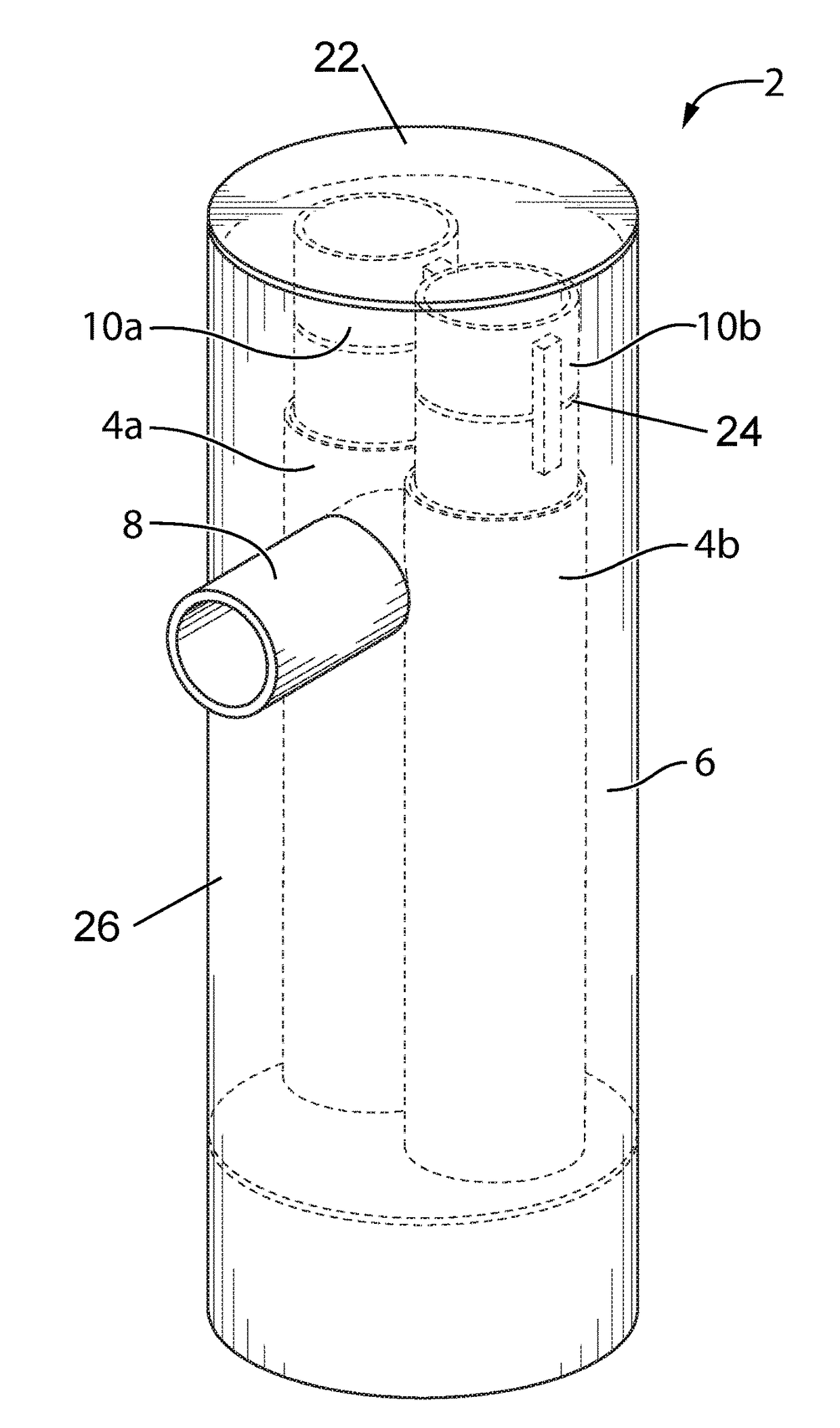
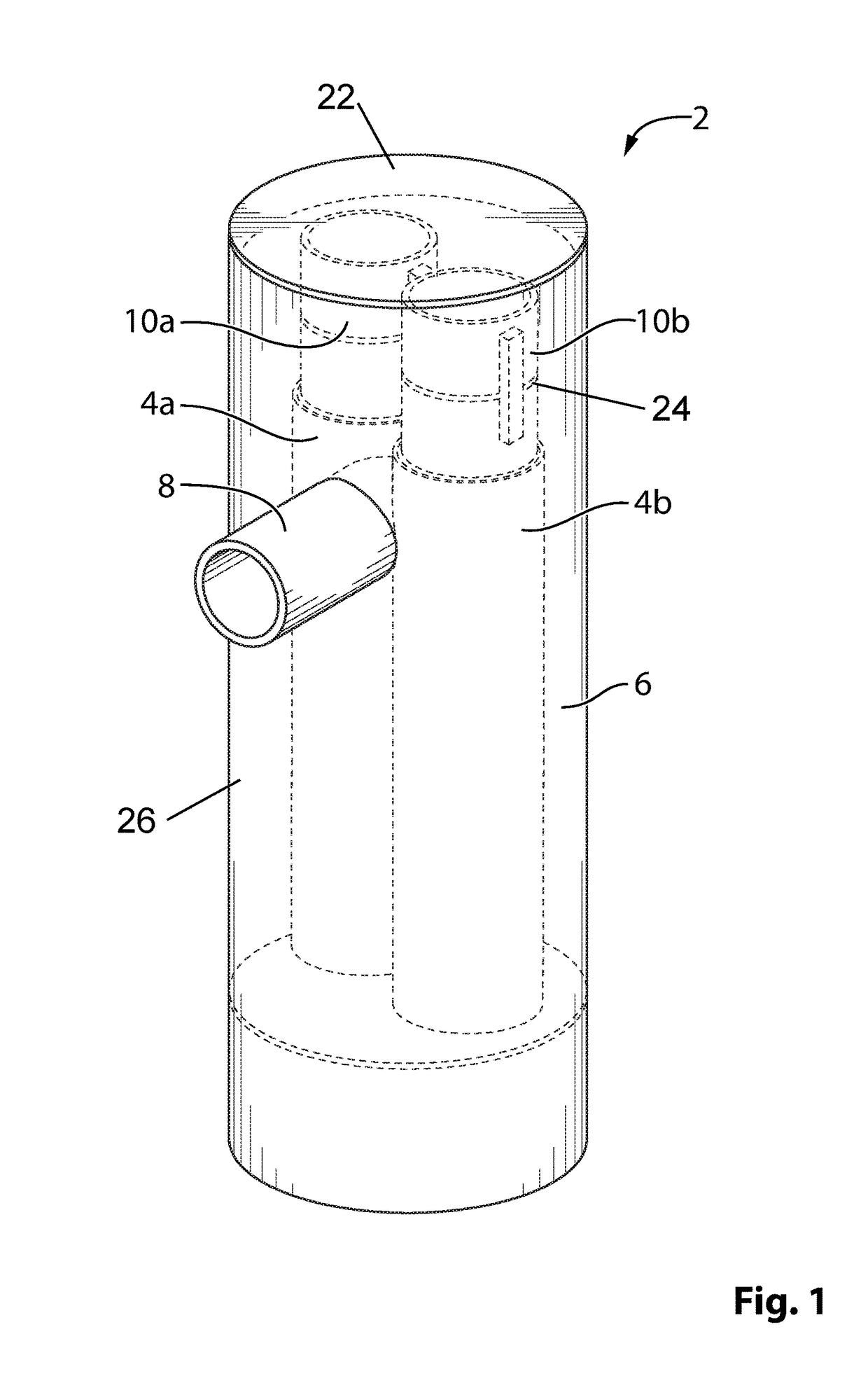
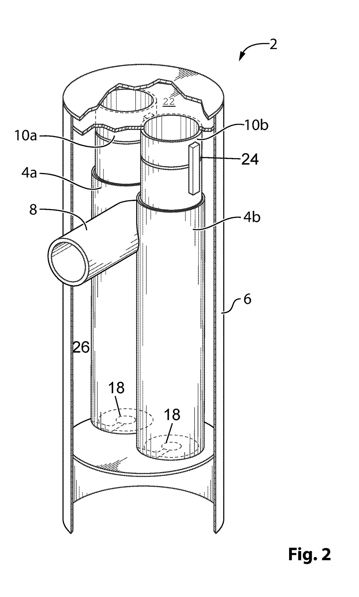
[0021]With reference to the figures, the present invention provides a dual cyclonic separator system 2 having a common tangential inlet. The present separator system 2 combines two cyclonic separators or cyclonic chambers 4a, 4b in parallel, having a single common involute / tangential inlet 8. The pair of cyclonic chambers 4a, 4b are placed within a shell 6. The shell 6 preferably takes the shape of a vertically oriented cylinder, although it would be possible for the shell to take on other shapes such as a vertically oriented rectangular prism, without departing from the scope of the present invention.

[0022]The indi...


PUM

PropertyMeasurementUnit
Lengthaaaaaaaaaa
Electrical resistanceaaaaaaaaaa
Volumeaaaaaaaaaa

Abstract

A cyclonic separator is taught, comprising at least two cyclonic chambers in the form of cylindrical tubes, having an upper inlet end and a lower liquid outlet end, a common tangential inlet in fluid communication with the upper end of each of the at least two cyclonic chambers, a gas outlet proximal to and extending upwardly from the upper ends of each of the at least two cyclonic chambers and a common outer shell surrounding the at least two cyclonic chambers, wherein said common tangential inlet extends through said common outer shell and into each of said at least two cyclonic chambers. A method for separation of a mixed heavy phase / light phase process stream is also taught.

Description

FIELD OF THE INVENTION[0001]The present invention relates to cyclone separators for separating liquids from gases.BACKGROUND OF THE INVENTION[0002]Cyclonic separator systems are commonly used to segregate immiscible phases of a process stream, such as when a process stream comprises a mixed liquid phase and gas phase. Separator systems are commonly used to separate immiscible entrained liquids from a gas phase of a mixed gas / liquid process stream, wherein the process stream enters cyclonic chambers through inlets that are tangential to the curvature of each of the cyclonic chambers. As a result of the velocity and the tangential angle at which the liquid / gas process stream enters the cyclonic chamber, centrifugal forces act on the process stream and cause it to spin around the curvature of the cyclonic chamber.[0003]Centrifugal forces acting on each of the immiscible phases in the process stream, cause the phases to move either away from or towards the centre of the cyclonic chamber...

Claims


Application Information

Patent Timeline
IPC IPC(8): B01D19/00B04C5/04B04C5/30B04C5/28
CPCB01D19/0057B04C5/30B04C5/04B04C5/28B04C5/08
Inventor ERNST, KENNETH ALFREDGREEN, MATTHEW JAMESKOCKEN, MORLEY EVERETTCONNOLLY, BRENDAN ALEXANDER
Owner JCI CYCLONIC TECH LTD
Why Eureka
Eureka Blog
Learn More