Inline power generator

a power generator and inline technology, applied in the direction of machines/engines, sustainable buildings, mechanical equipment, etc., can solve the problems that the supply and production system requires a significant amount of energy, and achieve the effects of enhancing efficiency, reducing turbulence, and being more responsiv

Inactive Publication Date: 2018-02-08
SPINERGY PTY LTD
View PDF10 Cites 5 Cited by
  • Summary
  • Abstract
  • Description
  • Claims
  • Application Information

AI Technical Summary

Benefits of technology

[0033]The baffles may be made as a separate part or attached along an internal wall of said fluid conduit for rotating the flow of fluid onto the impeller, thereby ensuring that the impeller rotates at maximum velocity, or at least is more responsive in a low flow environment.
[0034]The fluid in the pipe would normally run parallel to the axis, however, the inside surface of the coupling may be rifled to impart a rotation to the flow, in the same direction as the impeller rotates to enhance efficiency.
[0035]A means of streamlining fluid downstream of said impeller may additionally be positioned within the fluid path to minimize turbulence.

Problems solved by technology

These supply and production systems require a significant input of energy.

Method used


Image

  • Inline power generator
  • Inline power generator
  • Inline power generator

Examples


Embodiment Construction

[0071]There are numerous specific details set forth in the following description. However, from the disclosure, it will be apparent to those skilled in the art that modifications and / or substitutions may be made without departing from the scope and spirit of the invention. In some circumstance specific details may have been omitted or enlarged so as not to obscure the invention. Similar reference characters indicate corresponding parts throughout the drawings.

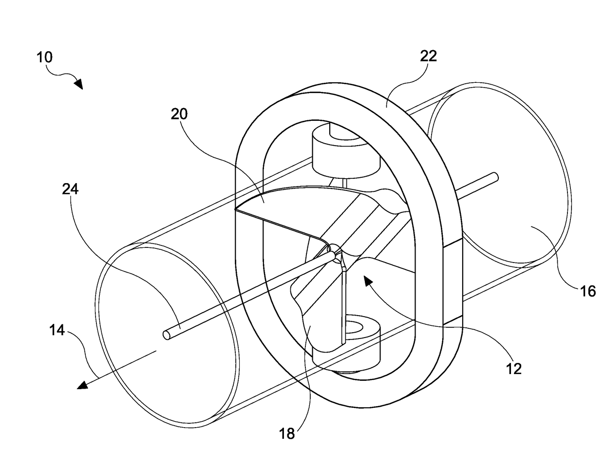
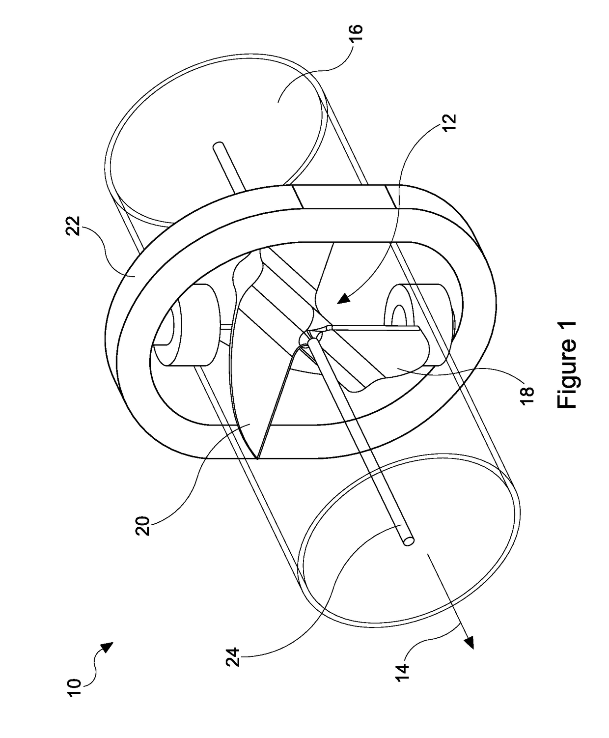
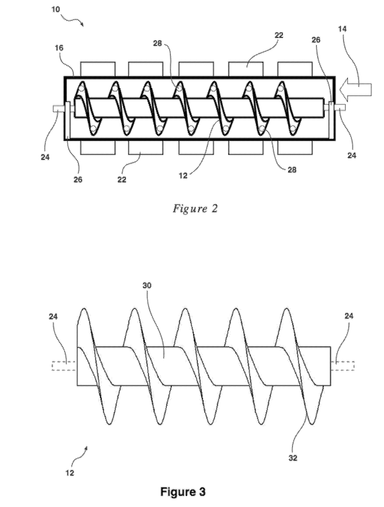
[0072]Turning to the figures for a detailed explanation of the invention, there is illustrated a power generating apparatus 10 demonstrating, by way of examples, arrangements in which the principles of the present invention may be employed. As illustrated in FIG. 1 the power generating apparatus 10, includes a rotatable impeller 12 locatable within the flow path 14 of the conduit 16. The conduit may be a pressurized water (or other liquid) pipe or gas line. The vanes or fins 18, 20 of the impeller 12 are oppositely charged as i...


PUM

PropertyMeasurementUnit
electrical currentaaaaaaaaaa
pressureaaaaaaaaaa
pressuresaaaaaaaaaa

Abstract

An electrical generator, comprising a rotatable impeller locatable within a flow path of a conduit. The impeller is rotated by fluid flowing along said flow path. The impeller comprises a magnetic portion, the generator further including a stator located external of the flow path. The stator generating electrical power in response to rotation of the magnetic portion.

Description

[0001]This application is a continuation in part of U.S. patent application Ser. No. 14 / 422,157, filed on 17 Feb. 2015, which is a national stage entry application of International Application No. PCT / AU2013 / 000921, filed on 19 Aug. 2013, and which claims priority to Australian Patent Application No. 2012903553, filed on 17 Aug. 2012, wherein the specifications and contents of which are hereby incorporated herein by reference in their entirety.BACKGROUND OF THE INVENTIONField of the Invention[0002]The present invention relates to the generation of electricity using an inline impeller positioned in a flow path of a conduit, and a stator positioned externally of the flow path.Description of the Related Art[0003]Supply systems including water and gas lines are typically provided at pressure to ensure delivery to the end user. Elevated pressures are required for the delivery however such pressures are often not required by the end user. Similarly in facilities for the production or deli...

Claims


Application Information

Patent Timeline
Patent Type & Authority Applications(United States)
IPC IPC(8): F01D1/02F01D15/10
CPCF01D1/02F01D15/10F05D2220/768F05B2240/121Y02B10/50F01D1/38F03B13/00H02K7/1823H02K15/00F05B2220/20F05B2220/602F05B2220/7066F05B2250/25Y10T29/49009
Inventor RUBINSHTEIN, PETERSOPER, KEVIN JAMESLEAHY, MALCOLM FREDERICK
Owner SPINERGY PTY LTD
Why Eureka
Try Eureka