Medical simulator apparatus and method

a simulator and simulator technology, applied in the field of medical simulators, can solve the problems of inability to mimic the feel, reflexes, tightening of human tissue, and general lack of genuine touch and feel of current mds systems

Inactive Publication Date: 2006-06-08
PODLASEK ROBERT J +1
View PDF6 Cites 32 Cited by
  • Summary
  • Abstract
  • Description
  • Claims
  • Application Information

AI Technical Summary

Benefits of technology

[0009] The invention is a simulator having electroactive polymer components and a control system connected to those components. The electroactive polymers (EAPs) have certain characteristics that may be changed with a given electrical input including but not limited to displacement of geometrical dimensions, exertion of mechanical force, elasticity, ductility, density and electrical resistance and capacitance. The control system can statically or dynamically change the electrical input to the EAPs. By matching the characteristics of the electro active polymers to known characteristics of human tissue, a more life-like MDS system is achieved. By controlling the characteristics of the electroactive polymers with the control system, the MDS system will exhibit more life-like responses for a given stimuli.

Problems solved by technology

However, current MDS systems generally lack a genuine touch and feel of a real patient.
They cannot mimic the feel, reflexes, or tightening of human tissue.

Method used


Image

  • Medical simulator apparatus and method
  • Medical simulator apparatus and method
  • Medical simulator apparatus and method

Examples


first embodiment

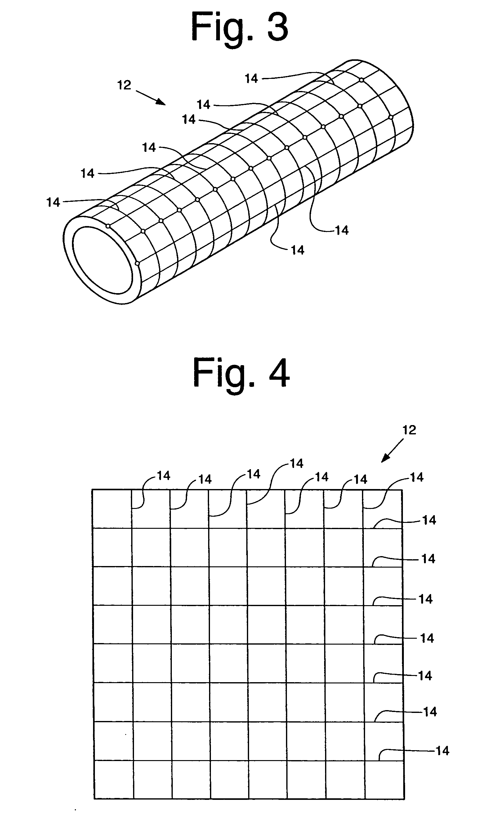
[0035]FIG. 3 illustrates a matrix of the polymer layer 12 with the electroactive fiber 14. The matrix is in the shape of a tube like a blood vessel with several longitudinal and transverse fibers thereon.

[0036]FIG. 4 is an array of fibers 14 embedded within a polymer layer 12. In the depicted embodiment, the matrix has a square or rectangular shape. Such a structure may mimic the walls of large organs, skin or muscle walls.

[0037]FIG. 5 depicts an array wherein activating fibers 14 are interspersed with sensors 20, either in alternating squares or in all squares as shown in FIG. 5, which may be attached to a separate circuit and provide feedback to a control system.

third embodiment

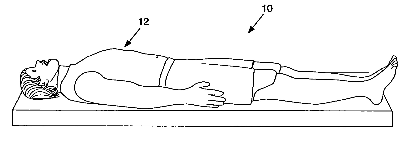
[0038]FIG. 6 is the matrix with the array of FIG. 4 in a shape of a pouch or other closed or open shell, hollow or otherwise, that may mimic a human organ. The various combinations of the tube matrix, the square or rectangular array matrix or the bag may be used to simulate an entire human organ. The various matrixes may be assembled together in the MDS system 10 as shown in FIG. 1.

Control System

[0039]FIG. 7 illustrates a control system 100 for use in conjunction with the MDS system 10. The control system includes a computer having a microprocessor 110, an amplifier 112, a medical simulation device 114 such as a probe. The computer 110 is connected to the amplifier 112. The amplifier is connected to the MDS system 10, and specifically to the electrodes 13. The computer 110 sends a signal to the amplifier 112, which in turn sends a signal to the appropriate electrode to selectively activate or deactivate a specific electroactive fiber or group of fibers. The fibers' characteristics...


PUM


Abstract

An animal simulator having electroactive polymer assemblies and a control system connected to the assemblies is disclosed. An animal simulator is constructed and arranged to mimic selected anatomy. It includes a substrate; an electroactive polymer assembly, within the substrate, the electroactive polymer assembly being comprised of at least one electroactive polymer and at least one electrode. A circuit is in operative communication with the electrode such that the electroactive polymer assembly deflects upon receipt of a signal through the circuit. The deflection simulates anatomy. The animal simulator further comprising a sensor, within the simulator, with the sensor being in operative communication with the circuit.

Description

CROSS-REFERENCE TO RELATED APPLICATIONS [0001] This application claims the benefit of U.S. Provisional Application No. 60 / 633,064, filed Dec. 3, 2004.BACKGROUND OF THE INVENTION [0002] 1. Field of the Invention [0003] The present invention relates to medical teaching simulators and, more particularly, to a medical teaching simulator utilizing an electroactive polymer. [0004] 2. Related Art [0005] Model-driven simulators (MDS) for medical training, sometimes known as high fidelity simulators, are simulators that use a manikin body or part of a body to physically represent a patient. The simulators have physiologic and pharmacologic models that direct real time autonomous reactions to interventions and therapies. MDS systems generally integrate multiple system models to produce an analogous patient response to interventions, such as surgery or placement of a stent or probe. [0006] MDS systems can be used to teach normal and abnormal physiology and pharmacology, equipment usage, patien...

Claims


Application Information

Patent Timeline
Patent Type & Authority Applications(United States)
IPC IPC(8): G07F11/00
CPCG09B23/28G09B23/30
Inventor PODLASEK, ROBERT J.PATTON, ARNOLD
Owner PODLASEK ROBERT J
Why Eureka
Try Eureka