Dithering scheme using multiple antennas for OFDM systems

a technology of digital audio and multiple antennas, applied in the field of wireless transmission, can solve the problems of severe and rapid fluctuations in the received signal strength, multipath propagation, phase and amplitude constructive and/or destructive addition, etc., to achieve the effect of improving the bit error rate of fading sub-channel information without significantly affecting the overall performance of ofdm demodulator, and reducing the length of fading

Inactive Publication Date: 2009-05-05
AVAGO TECH INT SALES PTE LTD
View PDF31 Cites 34 Cited by
  • Summary
  • Abstract
  • Description
  • Claims
  • Application Information

AI Technical Summary

Benefits of technology

[0010]In accordance with the present invention, a ground- or roof-top-based repeater in an OFDM system uses multiple transmission antennas to retransmit the satellite signals. By using multiple transmission antennas, multiple identical OFDM signals are transmitted. Dithering is performed by introducing a slight variable-frequency phase offset to all but one of the multiple identical transmitted OFDM signals, and thus the effective overall channel is more dynamic and provides spatial diversity to minimize long periods of fading in fading subchannels of the OFDM signals when the receiver is in a slow moving or stationary situation. In accordance with an embodiment of the present invention, the variable-frequency phase offset is generated using the phase of the Rayleigh process.
[0011]This dithering process improves the bit error rate of the fading sub-channel information without significantly affecting the overall OFDM demodulator performance when the vehicle is slow-moving or stationary. Introducing a variable-frequency phase offset at all but one of the multiple transmission antennas makes the overall channel response more dynamic i.e., the dithering increases the effective channel response between the repeater transmitting the signals and the receiver. A variable-frequency phase offset will provide a more random-like channel response, instead of a periodic channel response that results when a fixed frequency offset is used.
[0012]To overcome the additional cancellation problem that can occur when two or more of the transmitting antennas are in a line-of-site position with the receiver and approximately the same distance from the receiver, a delay is deliberately introduced to make the delayed signal(s) appear to be reflected signals. This delay will not negatively impact the OFDM receiver performance as long as the delay is within the guard interval used in the OFDM process.

Problems solved by technology

A major obstacle to achieving efficient and reliable data communications over traditional radio frequency channels in urban areas is multipath propagation, also called multipath fading.
This can happen when, for example, there are signals reflected off of buildings, trees, other vehicles, etc. that arrive at the receiver at the same or different times. The interference of these signals, each having traveled a different distance, results in phase and amplitude constructive and / or destructive addition.
This can result in severe and rapid fluctuations in the received signal strength, particularly with a mobile receiver as it is moved.
While this decreases the problems caused by deflected signals, it does not eliminate the problem altogether and thus multipath fading and its associated problems persists.
If a deep fade (a fading signal where the signal-to-noise ratio is very low) occurs during the transmission of such a signal, then the bits that are transmitted during the deep fade cannot be received correctly.
When conditions are such that one or more of the sub-channels experiences a severe fading problem, problems still occur in the overall channel (the complete signal) when the sub-channels experiencing the fade contain information critical to the transmission, for example, synchronization information.

Method used


Image

  • Dithering scheme using multiple antennas for OFDM systems
  • Dithering scheme using multiple antennas for OFDM systems
  • Dithering scheme using multiple antennas for OFDM systems

Examples


Embodiment Construction

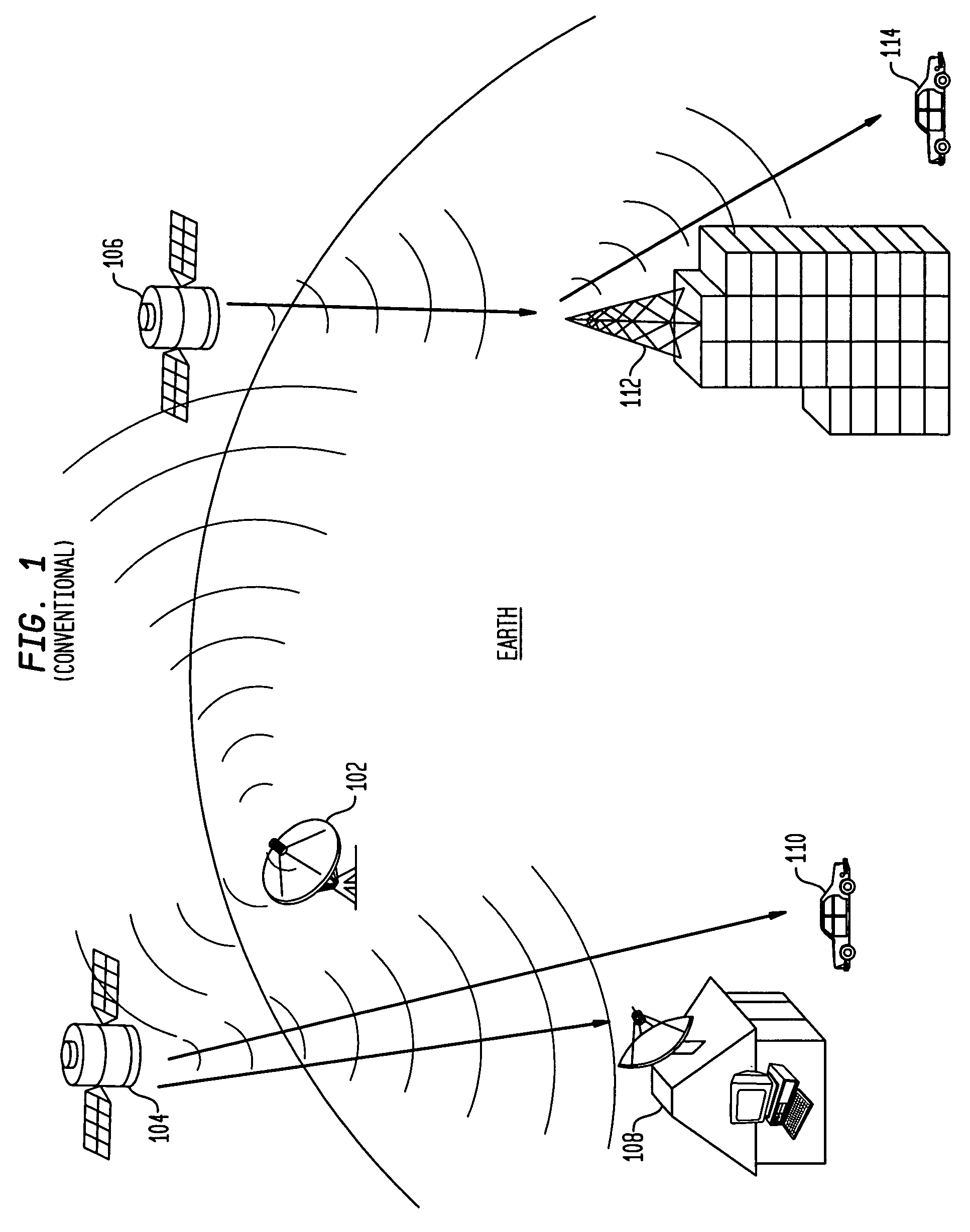
[0017]FIG. 1 illustrates a conventional satellite radio system. An earth station 102 is utilized to broadcast content to satellites 104 and 106. In the example illustrated in FIG. 1, satellite 104 reflects the transmitted content back to earth to a wide area, including the vicinity of a residence 108 and a vehicle 110. Assuming that residence 108 and vehicle 110 are equipped with appropriate receiving equipment, each will receive the satellite transmission containing the content and be able to listen to the content being broadcast. Since residence 108 is stationary, the receiver in residence 108 will continue to receive the transmitted content as long as satellite 104 remains within range of residence 108.

[0018]Since vehicle 110 will typically be mobile and moving from one location to another, vehicle 110 will only receive the transmitted broadcast as long as it is within range of satellite 104 or another satellite in the system. However, even with a single satellite in the system, ...


PUM


Abstract

A ground-or roof-top-based repeater in an OFDM system uses multiple transmission antennas to retransmit satellite signals. By using multiple transmission antennas, multiple identical OFDM signals are transmitted. Dithering is performed by, using a phase of Rayleigh process generator, introducing a slight variable-frequency phase offset to all but one of the multiple identical transmitted OFDM signals, and thus the effective overall channel is more dynamic and provides spatial diversity to minimize long periods of fading in fading subchannels of the OFDM signals when the receiver is in a slow moving or stationary situation. To overcome the additional cancellation problem that can occur when two or more of the transmitting antennas are in a line-of-site position with the receiver and approximately the same distance from the receiver, a delay is deliberately introduced to make the delayed signal(s) appear to be reflected signals. This delay will not negatively impact the OFDM receiver performance as long as the delay is within the guard interval used in the OFDM process.

Description

FIELD OF THE INVENTION[0001]This invention relates to wireless transmissions and, more particularly, to a method and system for improving the performance of satellite digital audio radio systems.BACKGROUND OF THE INVENTION[0002]Satellite radio is an emerging technology that is in the early stages of gaining consumer acceptance. Major electronics manufacturers such as Pioneer, Alpine, Carion, Delphi Delco, Sony, and Motorola and automobile companies, such as General Motors and Honda, are partnering with satellite radio providers to bring satellite radio to the consumer. Satellite radio enables users to subscribe to a service by which high quality audio content, free of the interference often accompanying traditional radio frequency (RF) broadcast systems, is available via satellite transmission. In addition, in vehicular use, satellite radio enables a vehicle equipped with the appropriate receiving equipment to hear the same station regardless of the vehicle location, i.e., a vehicle...

Claims


Application Information

Patent Timeline
Patent Type & Authority Patents(United States)
IPC IPC(8): H04B1/00H04J11/00H04B7/005H04B7/02H04B7/06H04B7/185
CPCH04B7/0671H04B7/0682H04B7/18517H04W52/34
Inventor CELEBI, SAMELSONG, JIEYUN, PAUL M.
Owner AVAGO TECH INT SALES PTE LTD
Why Eureka
Try Eureka