
Method of controlling a power network

a power network and power technology, applied in the direction of adaptive control, greenhouse gas reduction, instruments, etc., can solve the problems of severely constraining management, effectively wasting the additional power that it is capable of producing,

Active Publication Date: 2014-05-22
SIEMENS GAMESA RENEWABLE ENERGY AS
View PDF23 Cites 27 Cited by
  • Summary
  • Abstract
  • Description
  • Claims
  • Application Information

AI Technical Summary

Benefits of technology

The invention is a method for optimizing the production and storage of power in a power network, by using the fact that some power generation facilities can produce more power than they need during certain phases. The method makes use of this excess power, and can store it for later use or sell it to the grid operator. The method can also provide inertial response services to the grid operator, and can smoothen out power production fluctuations. Additionally, the method can provide fast ramping power to retain balance on the grid, while also minimizing energy spilled by the plant. The revenue projection is based on various forecast variables, such as wind speed, energy production, energy price, spinning reserve price, and ramping capability price. The method allows for the optimal trade-off between energy production, storage, and sale, making the power network more efficient and profitable.

Problems solved by technology

In certain situations, such a conventional “renewable” power plant may have the potential to produce more power than is actually needed, but since the power plant may only generate as much power as is required to fulfil a grid demand, the additional power that it is capable of producing is effectively wasted since it cannot be fed into the grid.
However, the management of power storage facilities in isolation from the power generation plants means that these cannot be operated to optimally utilize their capabilities, and their management is also severely constrained by limitations imposed by grid requirements.

Method used


Image

  • Method of controlling a power network
  • Method of controlling a power network
  • Method of controlling a power network

Examples


Embodiment Construction

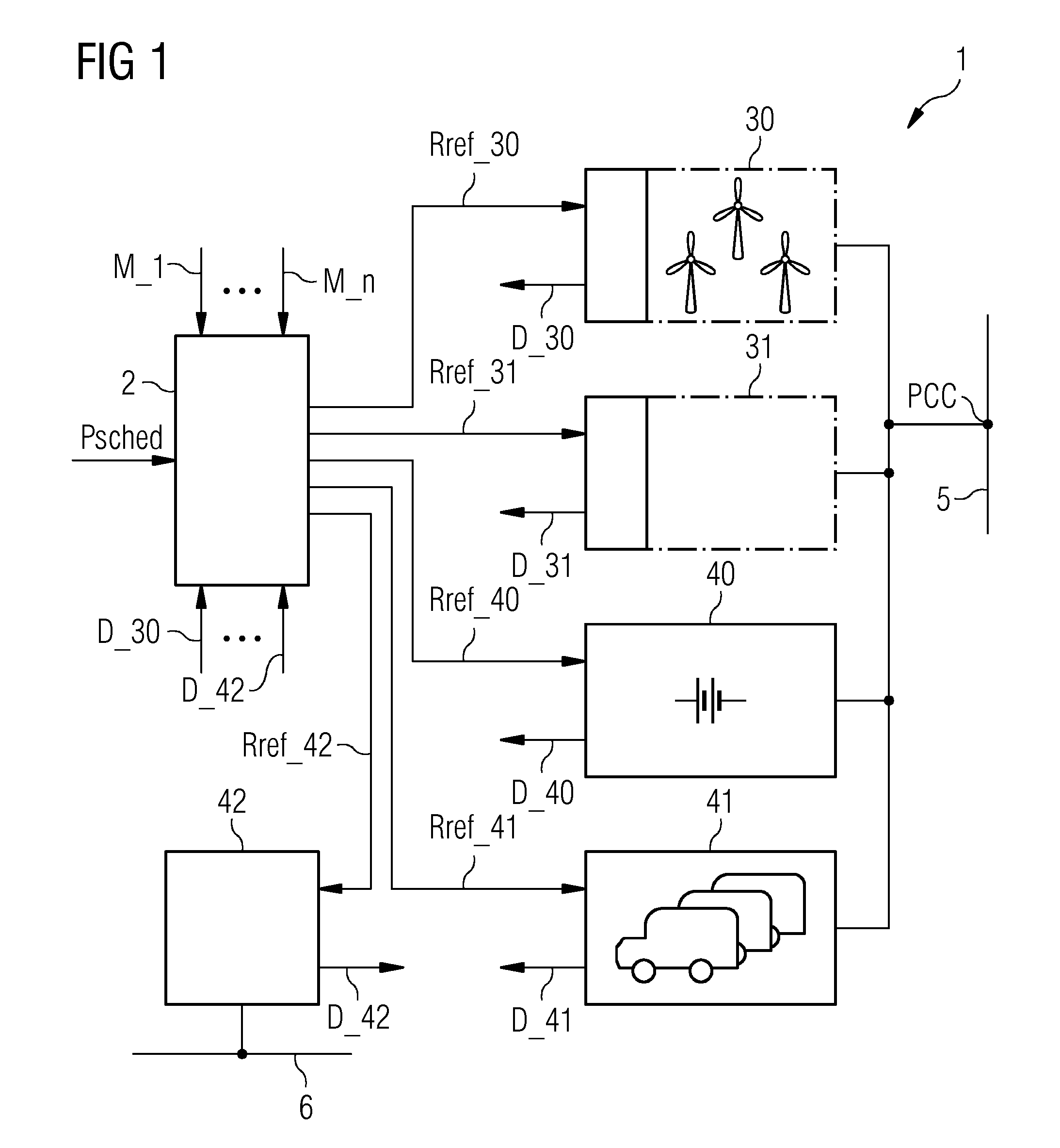
[0041]In the diagrams, like numbers refer to like objects throughout. Objects in the diagrams are not necessarily drawn to scale.

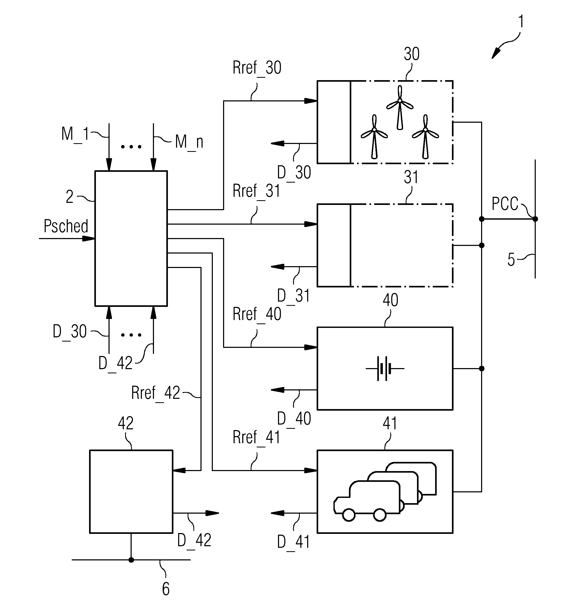
[0042]FIG. 1 shows a block diagram of a power network 1 according to an embodiment of the invention. The power network comprises various power generation plants 30, 31 and various power storage facilities 40, 41, 42. Power that is output by the power generation plants 30, 31 and a reversible power storage facility 40 is collected at a point of common connection PCC for feeding into an electricity grid 5. Surplus power generated by the power generation plants 30, 31 can be transferred to non-reversible power storage facilities 41, 42 such as the batteries 41 of a fleet of electric vehicles, or a synthetic natural gas plant 42, which in this embodiment is realised to supply gas to a consumer gas grid 6.

[0043]A power network controller 2 receives an input power reference Psched indicating the amount of electrical power required by the grid 5. The power networ...


PUM


Abstract

A method is provided for controlling a power network that includes a plurality of power generation facilities connected to an electricity grid and a plurality of power storage facilities connected to the power generation facilities. The method includes monitoring a production capacity of the power generation facilities, monitoring a storage capacity of the power storage facilities and determining an optimal facility control plan on the basis of the storage capacity and the production capacity. The method further includes operating the power network, according to the facility control plan, to feed power from the power generation facilities into the electricity grid and / or to transfer power from the power generation facilities to the power storage facilities and / or to consume power from the power storage facilities.

Description

FIELD OF INVENTION[0001]The invention describes a method of controlling a power network; a power network controller; and a power networkBACKGROUND OF INVENTION[0002]Conventional base load power production plants or facilities—for example nuclear power plants or fossil-fuel power plants—can deliver power as required to an electricity grid. A grid operator may determine the base load at any specific time, i.e. the amount of power required by customers supplied by the grid, and issue appropriate references to any power plant that feeds into the grid. Such power plants are generally characterized by a constant power output. In the case of power production plants that generate electricity using renewable energy sources such as wind energy or solar energy, the amount of power that can be output depends to some extent on the environmental situation, for example the strength of the wind in the case of a wind power plant; or the time of day and extent of cloud cover in the case of a photovol...

Claims


Application Information

Patent Timeline
IPC IPC(8): G05B13/02
CPCG05B13/02H02J3/28H02J3/38H02J7/0013H02J3/008G06Q50/06Y04S50/10Y02P90/50H02J2310/64H02J2300/20H02J3/381Y04S20/222Y02B70/3225H02J3/48H02J3/50H02J2300/22Y02E70/30
Inventor STOETTRUP, MICHAELNIELSEN, KAJ SKOV
Owner SIEMENS GAMESA RENEWABLE ENERGY AS
Learn More