Pressure regulating valve with flow Anti-rotation

Inactive Publication Date: 2018-02-15
HAMILTON SUNDSTRAND CORP
View PDF5 Cites 3 Cited by
  • Summary
  • Abstract
  • Description
  • Claims
  • Application Information

AI Technical Summary

Benefits of technology

The patent is for a pressure regulating valve that includes a sleeve with windows that help to control the pressure of the fluid inside the valve. The windows are made up of small holes that align with fluid flow. When the pressure at the inlet of the valve is higher than a certain level, a piston moves to open the valve and allow fluid to flow through. This design helps to ensure consistent and accurate pressure regulation.

Problems solved by technology

As a result, the pressure regulating valves arranged within the fluid housing are not interchangeable with other systems because the anti-rotation device (or lack thereof) of each is dependent on the housing arrangement.

Method used


Image

  • Pressure regulating valve with flow Anti-rotation
  • Pressure regulating valve with flow Anti-rotation
  • Pressure regulating valve with flow Anti-rotation

Examples


Embodiment Construction

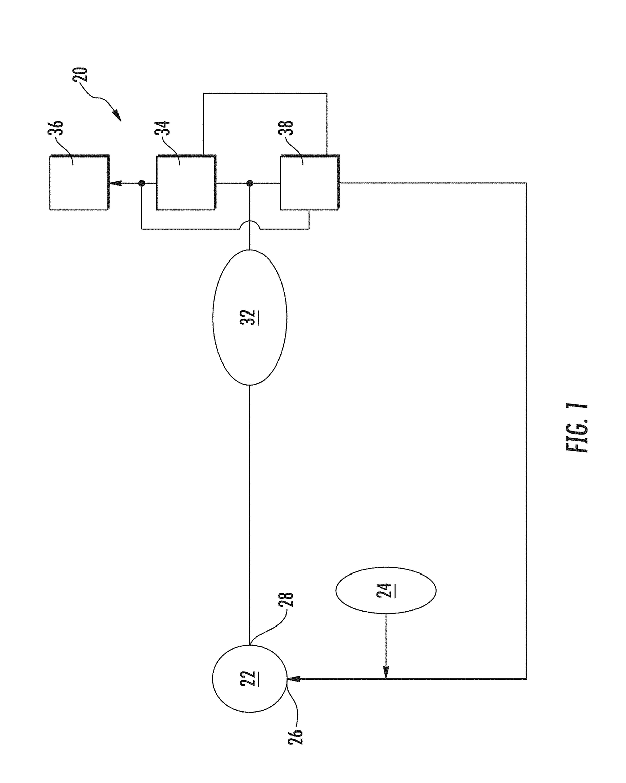
[0015]FIG. 1 is a schematic diagram of an aircraft fuel supply system 20 configured to supply fuel to an engine, such as the engine illustrated in FIG. 1 for example. The supply system 20 includes a fuel pump 22 that draws fuel from a fuel supply 24. The pump 22 has a pump inlet 26 in fluid communication with the fuel supply 24 and a pump outlet 28 in fluid communication with a metering valve 34 and a pressure regulating valve 38. Fuel passes through a filter 342 to remove contaminants therefrom. Fuel exiting the filter 32 is then directed to the metering valve 34 to supply fuel to an engine 36. The pressure regulating valve 38 receives pressure inputs from sense lines around the metering valve 34 to regulate the pressure across the metering valve 34. If the supply of fuel at the metering valve exceeds an amount necessary for the current operating condition of the engine, the pressure regulating valve returns the excess fuel to the pump inlet 26.

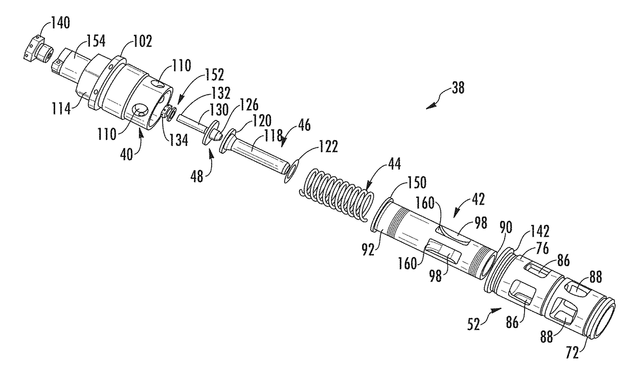
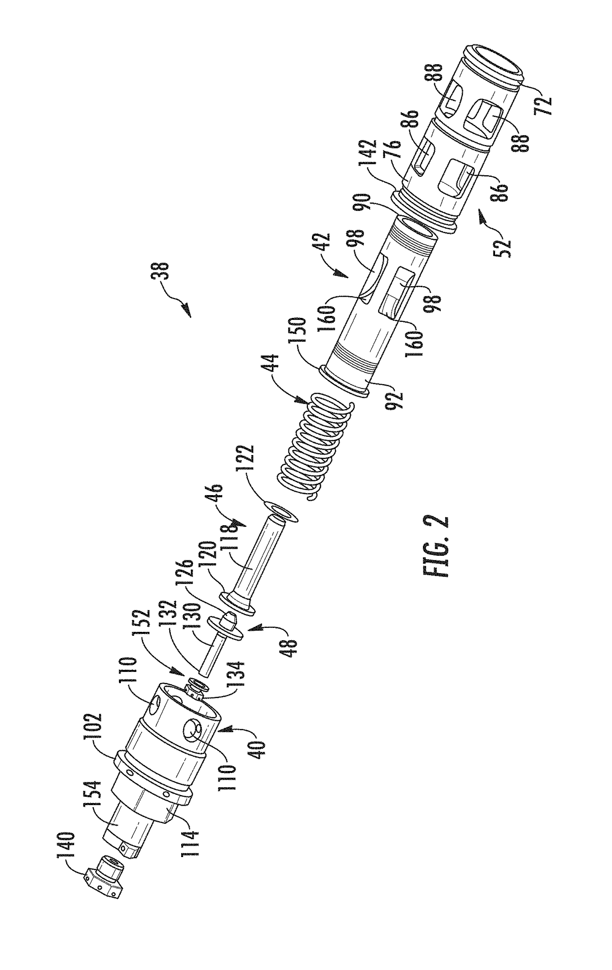
[0016]An example of a pressure regula...


PUM


Abstract

A sleeve for a pressure regulating valve includes a sleeve body surrounding a central axis and defined by an overall length extending from a first end to a second end. The sleeve body has a central sleeve bore extending from the first end to the second end. The sleeve body includes a first set of windows circumferentially spaced about the central axis and a second set of windows axially spaced from the first set of windows and circumferentially spaced about the central axis. Each window of the first set of windows is defined by a plurality of small holes.

Description

BACKGROUND OF THE INVENTION[0001]This invention generally relates to a pressure regulating valve, and more particularly, to a sleeve of a pressure regulating valve for use in a fuel line of an aircraft engine.[0002]Gas turbine engines are typically used to power an aircraft. A fuel system provides fuel to various portion of the gas turbine engine. The fuel system includes various valves such as a pressure regulating valve, a high pressure relief valve, and a filter bypass valve that cooperate with each other to supply fuel to the gas turbine engine in a controller and accurate manner.[0003]During operation of the fuel system, the pressure regulating valve commonly experiences a rotational force due to the fluid flow there through. In conventional assemblies, an anti-rotation device is positioned between the spool and the sleeve of the pressure regulating valve to minimize the effects of the rotational force, or not included if fluid housing does not cause flow rotation. The flow thr...

Claims


Application Information

Patent Timeline
IPC IPC(8): F02C7/232F16K3/24F16K31/122G05D16/10
CPCF02C7/232G05D16/106F05D2220/32F16K31/1221F16K31/1223F16K3/24F16K3/30G05D16/10G05D16/028
Inventor CORETTO, AUGUST M.RICKIS, AARON F.
Owner HAMILTON SUNDSTRAND CORP
Why Eureka
Try Eureka