

Image forming apparatus, cartridge, and frame body used for the cartridge
- Summary
- Abstract
- Description
- Claims
- Application Information
AI Technical Summary
Benefits of technology
Problems solved by technology
Method used
Image

Examples
first embodiment
[0029]An Outline of an Entire Structure of an Image Forming Apparatus
[0030]The Entire Structure of the Image Forming Apparatus
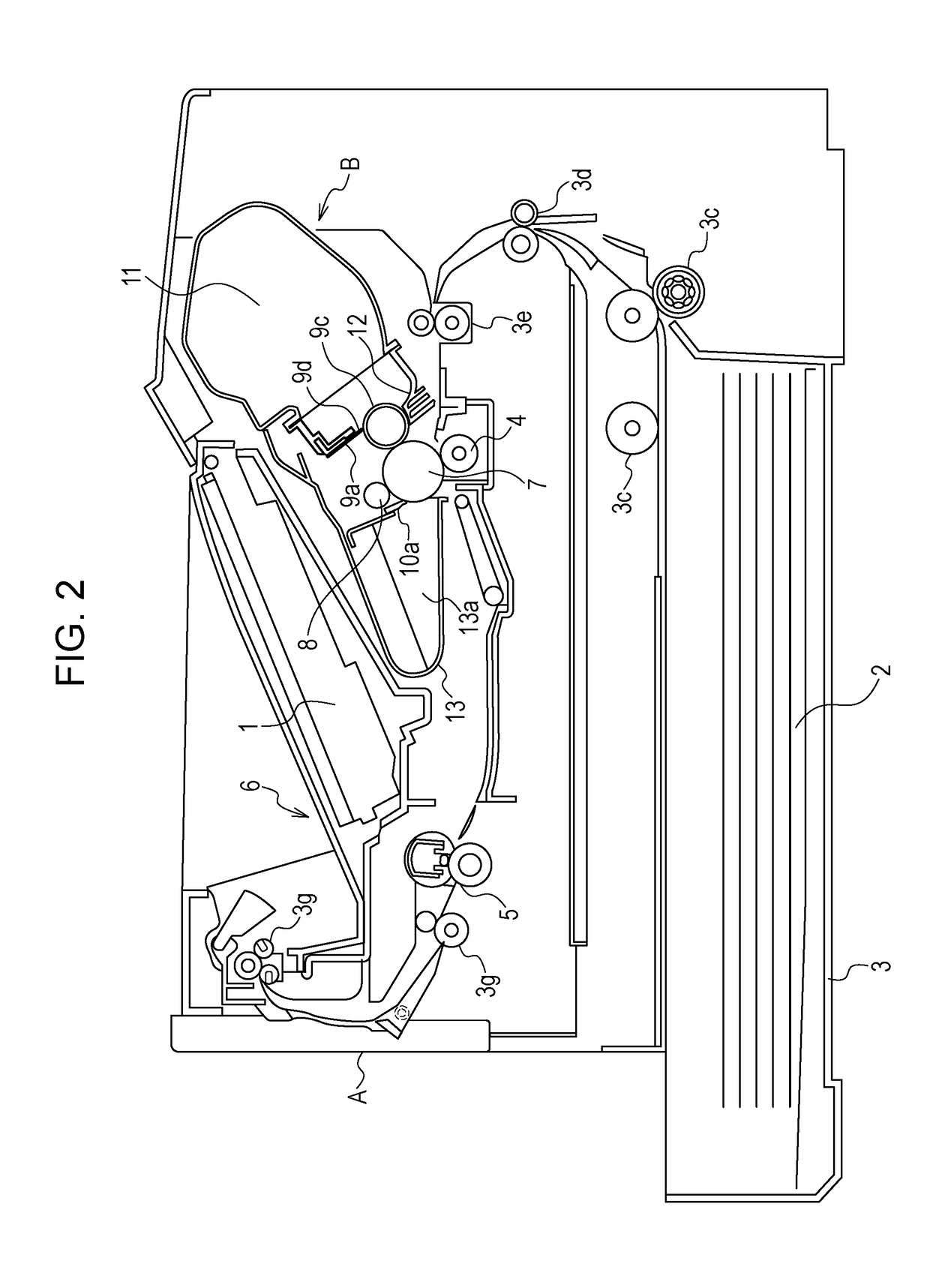
[0031]Initially, an outline of the entirety a main body A of an image forming apparatus (referred to as a “main body” hereafter) is described with reference to FIG. 2. As illustrated in FIG. 2, a process cartridge B that is attachable to and detachable from the main body is attached to the main body A. Here, the process cartridge refers to a cartridge into which a photosensitive drum and at least a developing device serving as a process device that performs operation on the photosensitive drum are integrated and which is attachable to and detachable from the main body A of the image forming apparatus.
[0032]A rotatable photosensitive drum 7 and process devices disposed around the photosensitive drum 7 are integrally provided in the cartridge B. The process devices around the photosensitive drum 7 include, for example, a charging roller 8, a developing roller 9...
second embodiment
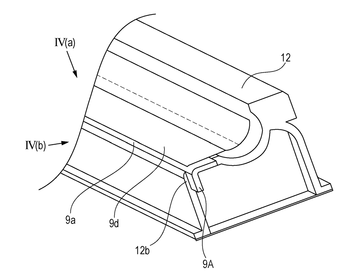
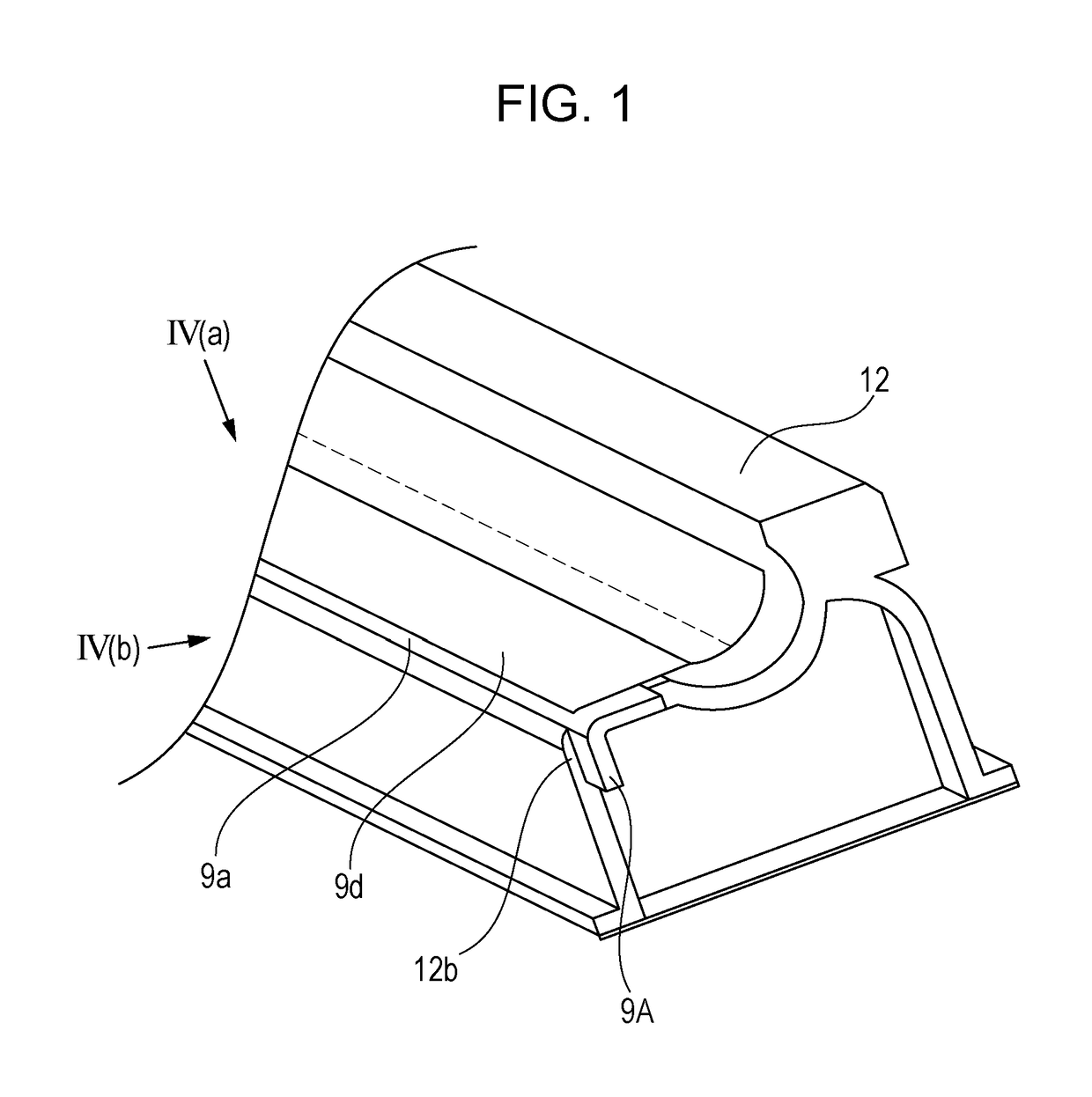
[0055]According to the first embodiment, the exposed portions 9A at both the ends of the first support member 9a in the longitudinal direction N and the first plate portion 9al are not embedded in the molten resin used to form the developing container 12. However, this is not limiting. As illustrated in FIG. 6, a structure is possible in which one of the end portions of the first support member 9a in the longitudinal direction N is not embedded in the molten resin used to form the developing container 12. In this case, a cushion member may be disposed at the one of the end portions of the first support member 9a so that the first support member 9a, the cushion member, and the developing container 12 are sequentially arranged in the longitudinal direction N. Furthermore, not only the second plate portion 9a2 but also the first plate portion 9a of the first support member 9a may be embedded in the molten resin used to form the developing container 12. In this case, the developing blad...
third embodiment
[0060]According to the first embodiment, the first support member 9a is secured at the securing portion 12b of the developing container 12, and the developing blade 9d is secured to the first plate portion 9a1 such that the developing blade 9d projects from the side of the first plate portion 9a1 connected to the second plate portion 9a2 toward the side opposite to the side of the first plate portion 9a1 connected to the second plate portion 9a2. However, this is not limiting. As illustrated in FIG. 7, the developing blade 9d may be secured to the first plate portion 9a1 of the first support member 9a such that the developing blade 9d projects from the side opposite to the side where the first plate portion 9a1 and the second plate portion 9a2 of the first support member 9a are connected to each other toward the side where the first plate portion 9a1 and the second plate portion 9a2 are connected to each other. Also, as illustrated in FIG. 7, it is sufficient that the exposed portio...
PUM
 Abstract
Description
Claims
Application Information