Support Device and Data Management Method

Active Publication Date: 2015-12-17
LINTEC CORP
View PDF5 Cites 1 Cited by
  • Summary
  • Abstract
  • Description
  • Claims
  • Application Information

AI Technical Summary

Benefits of technology

[0013]According to the present invention, a protecting member is attached to the distal end of the support shaft, and a shaft part is inserted into the protecting member, thereby protecting the shaft part. Therefore, a protrusion length of the shaft part can be made shorter by the length of the protecting member. Therefore, bending rigidity of the shaft part can be made higher than that in the above-described prior art, and bending of the shaft part by a load of a cylindrica

Problems solved by technology

This may deteriorate workability.
This may make a structure of the support shaft more complicated, and in addition, may cause increase in cost.
Here, for example, when the data carrier member includes a label-shaped IC tag in which an IC chip and an anten

Method used


Image

  • Support Device and Data Management Method
  • Support Device and Data Management Method
  • Support Device and Data Management Method

Examples


Example

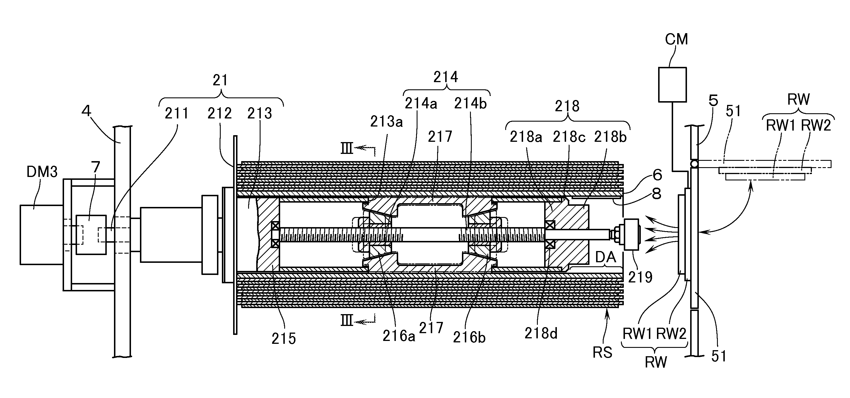
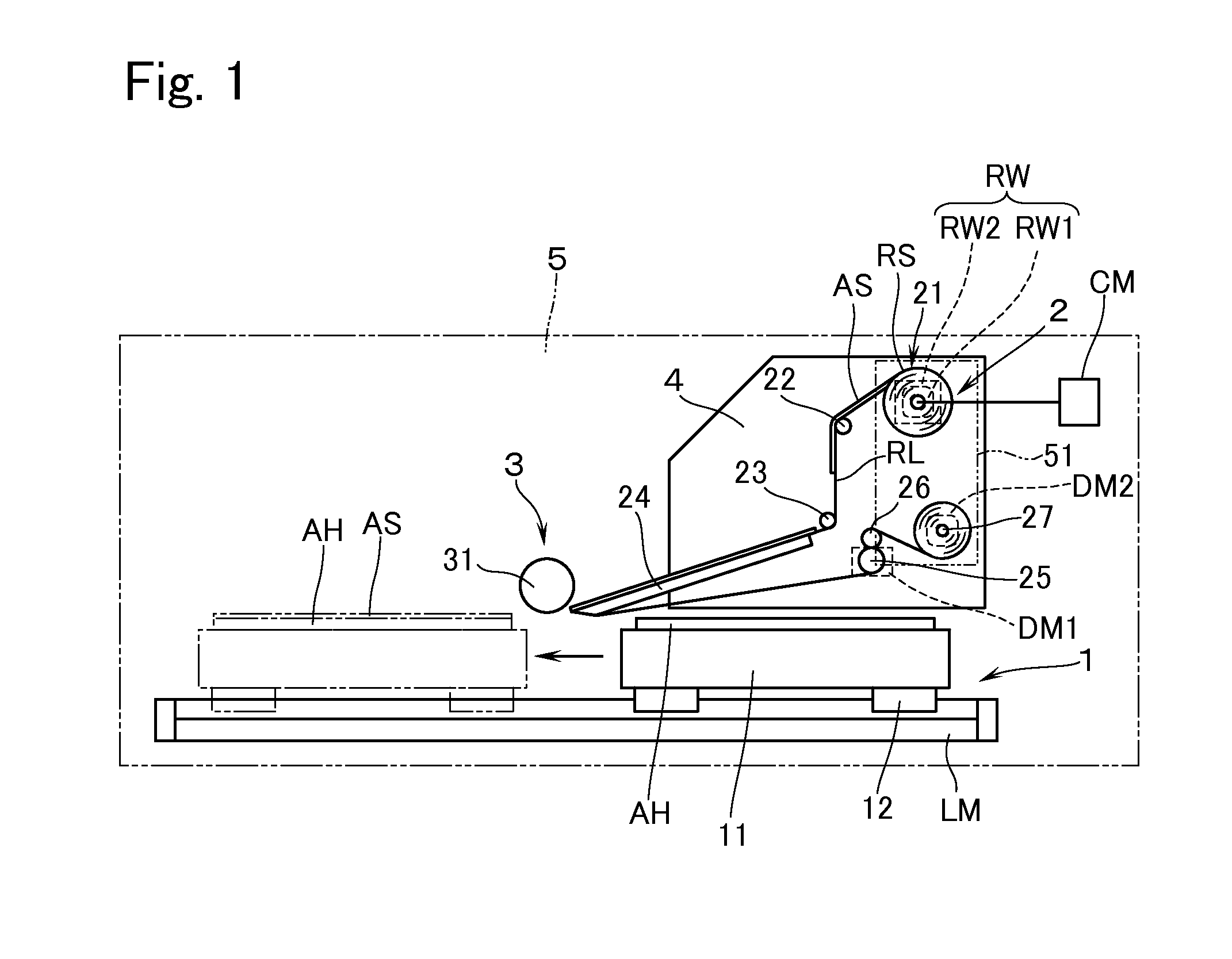
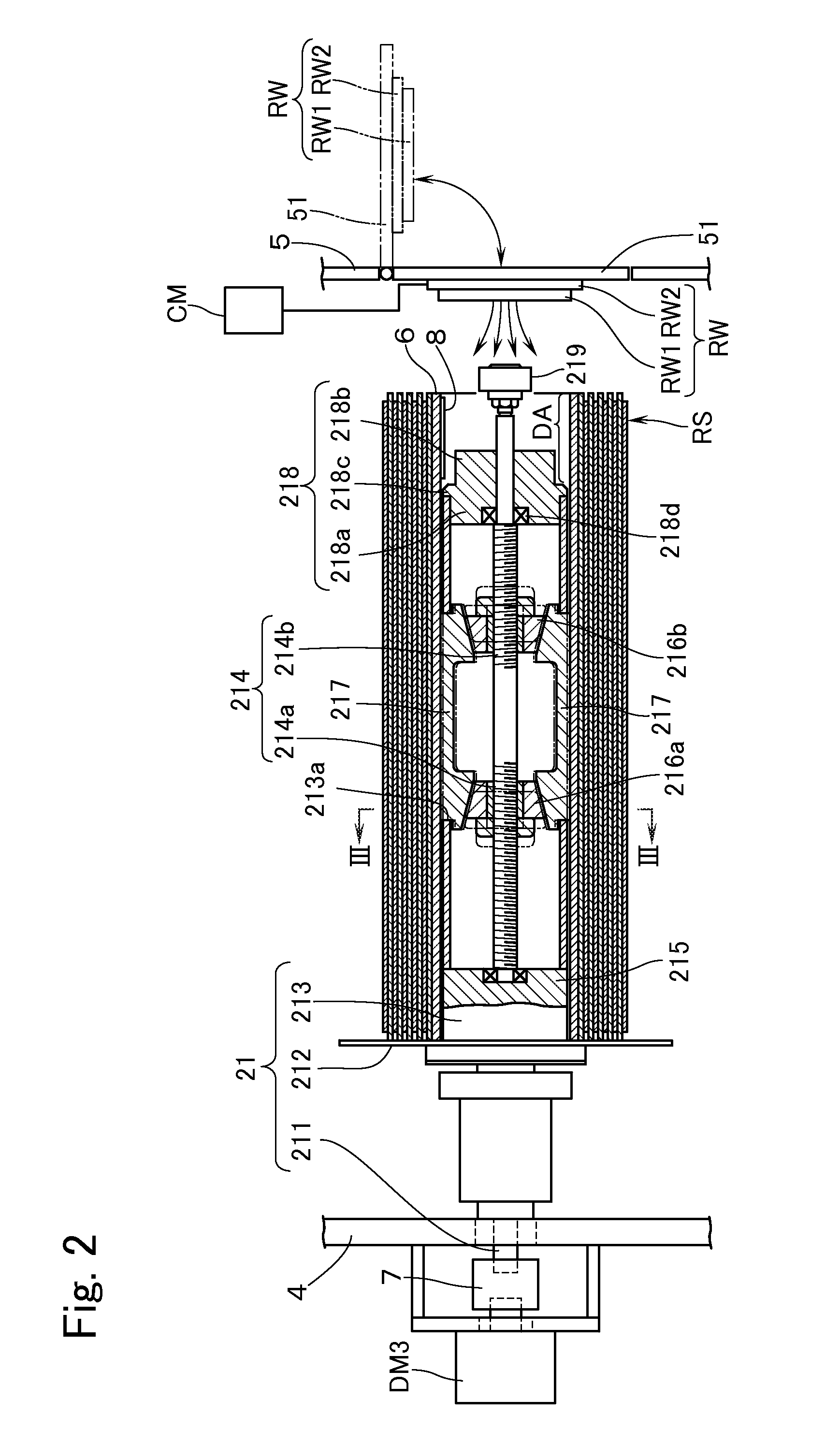
[0018]Hereinafter, an embodiment will be described with reference to the drawings using, as an example, a case in which a support device of the present invention is applied to a delivering part of a sheet sticking device which adheres an adhesive sheet AS to an adherend AH. Here, the terms “left”, “right”, “upper”, and “lower” to show the positions are based on FIG. 1 unless particularly indicated otherwise. A side where a support shaft, to be described later, is supported in a cantilevered state is referred to as a proximal end (front side or “this side” in FIG. 1), and a side opposite thereto is referred to as a distal end (back side in FIG. 1). The side of the distal end is referred to as “front” or “forward”, and the side of the proximal end is referred to as “rear”, if necessary.

[0019]With reference to FIG. 1, the sheet sticking or adhering device comprises: a conveying means 1 for conveying the adherend AH; a delivering means 2 for delivering a raw sheet RS as an elongated bod...


PUM

PropertyMeasurementUnit
Diameteraaaaaaaaaa

Abstract

A support device for supporting a cylindrical member around which is wound an elongated body has: a support shaft for supporting the cylindrical member that is fitted to an external surface of the support shaft from an opening on one end in a longitudinal direction of the cylindrical member; an anchoring plates, built into the support shaft, for anchoring the cylindrical member from an inner circumferential side of the cylindrical member; and an operating means having an operation shaft of a smaller diameter than the support shaft, the operation shaft protruding forward from a distal end of the support shaft in order to operate the anchoring plates. Further, the support device has a protecting member which is attached to the distal end of the support shaft and through which is inserted the operation shaft. The protecting member further has a reduced-diameter section smaller in diameter than the support shaft.

Description

TECHNICAL FIELD[0001]The present invention relates to a support device for supporting a cylindrical member around which is wound an elongated body, and also relates to a data management method for managing data relating to an elongated body wound around the cylindrical member by using the support device.BACKGROUND ART[0002]For example, a sticking device is known, in which an elongated body (raw sheet) having temporarily adhered on one of the release sheet an adhesive sheet or labels is wound around a cylindrical body; then on an adhesive sheet or a label temporarily bonded to one surface of a release sheet is wound around a cylindrical member; the elongated body is continuously delivered to thereby adhere on the surfaces of the adherend such as semiconductor wafers, containers or the like. When such a sticking device is used depending on different kinds in accordance with a type of the elongated body, it is desired in terms of production management to manage data on processing such ...

Claims


Application Information

Patent Timeline
IPC IPC(8): B65H16/04B65H18/02
CPCB65H16/04B65H2557/13B65H2301/4132B65H18/026B65H18/103B65H2301/51122B65H2403/52B65H2404/411B65H2701/194B65H75/2484
Inventor MATSUSHITA, KAORIYAMAGUCHI, KAZUHISAWATANABE, KENICHIOKAMOTO, NAOYA
Owner LINTEC CORP
Why Eureka
Try Eureka