Supercharge Your Innovation With Domain-Expert AI Agents!

Internal combustion engine

a technology of internal combustion engine and internal combustion chamber, which is applied in the direction of machines/engines, mechanical equipment, cylinders, etc., can solve the problems of increased vibration of the engine mount, loud engine noise, and vertical vibration of the internal combustion engine, so as to suppress the occurrence of twisting and bending, and increase the rigidity of the power plant

Inactive Publication Date: 2015-10-15
TOYOTA JIDOSHA KK
View PDF7 Cites 0 Cited by
  • Summary
  • Abstract
  • Description
  • Claims
  • Application Information

AI Technical Summary

Benefits of technology

The present invention provides an internal combustion engine with an increased rigidity of the power plant. This is achieved by optimizing the placement of the balance shaft housing to suppress twisting, bending, or other distortions caused by the opening of the crankcase. Oil pan side fastening areas and other fastening sections are used to secure the balance shaft housing, which results in increased rigidity of the power plant without adding much weight to the crankcase. A speed changing mechanism can also be disposed to further increase rigidity without interfering with the installation of other components. Overall, the internal combustion engine has improved rigidity and reduced vibrations and noise.

Problems solved by technology

Generally, in a multi-cylinder internal combustion engine, when rotational imbalance of a crankshaft is caused by a secondary inertia force that is generated by a vertical reciprocating motion of a piston, this further causes vertical vibration of the internal combustion engine.
In addition, due to a decrease in the rigidity of the power plant, vibration of an engine mount is increased, and consequently, the engine noise becomes louder.
However, there is space limitation in the rear of the crankcase for disposing the rib or the like because a space for fastening a drive plate and the like of the transmission is necessary in the rear of the crankcase.
In addition, if the rib and the like are disposed to reinforce the crankcase, it causes a disadvantage such as an increase in a mass of the crankcase.

Method used


Image

  • Internal combustion engine
  • Internal combustion engine
  • Internal combustion engine

Examples


Embodiment Construction

[0028]A description will hereinafter be made on an embodiment of an internal combustion engine according to the present invention with reference to the accompanying drawings.

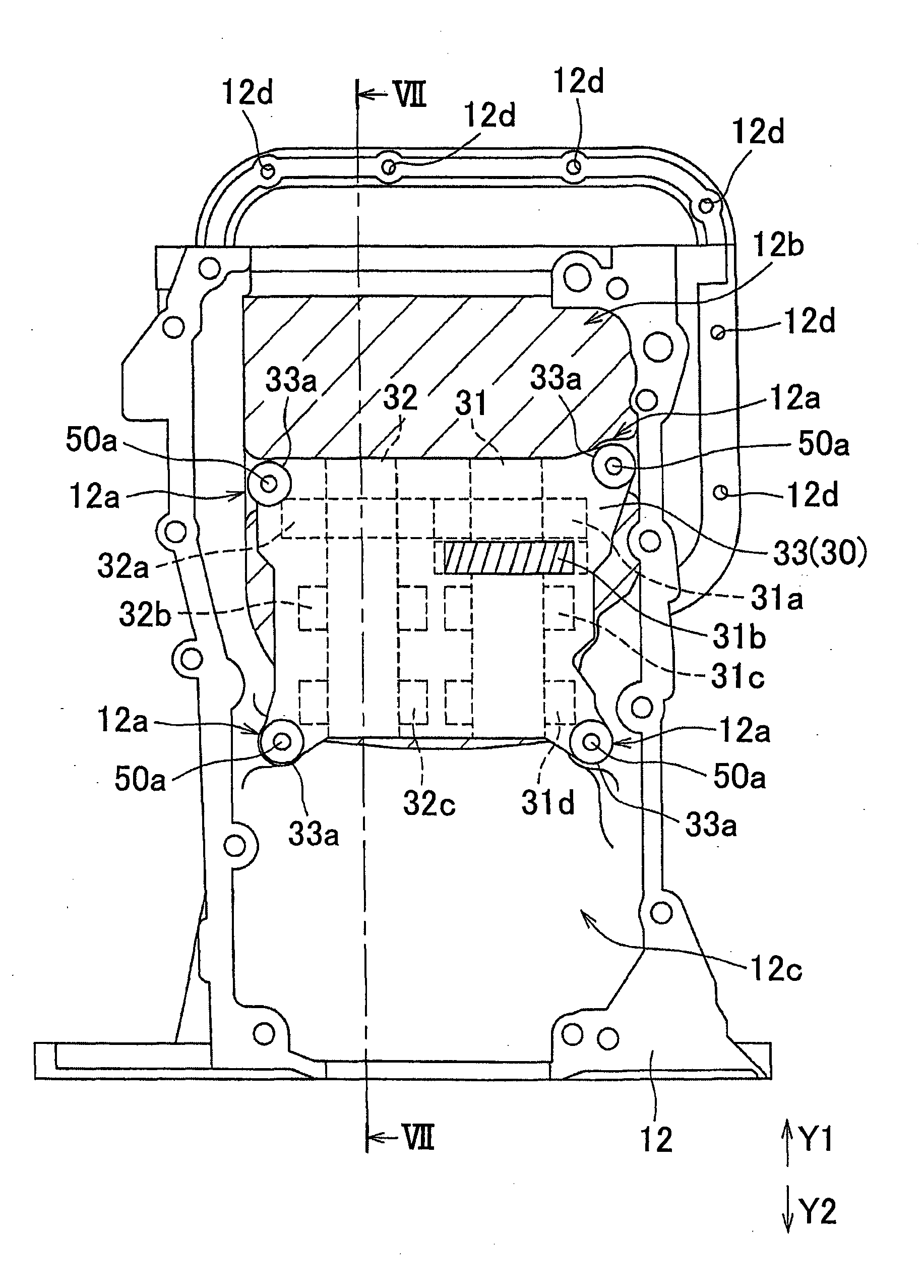
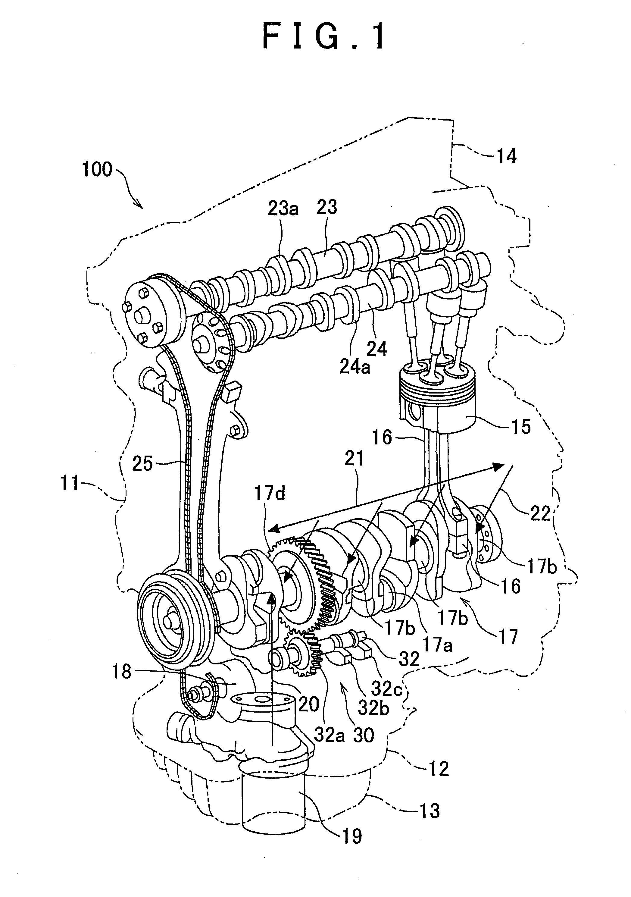
[0029]As shown in FIG. 1, an engine 100 includes a cylinder block 11, a crankcase 12, an oil pan 13, and a cylinder head 14. The engine 100 is an example of an “internal combustion engine” according to the present invention. The crankcase 12 is attached to a lower part of the cylinder block 11. The oil pan 13 is attached to a lower part of the crankcase 12. The cylinder block 11 is provided with four cylinders (not shown), and a piston 15 is housed in each of the cylinders.

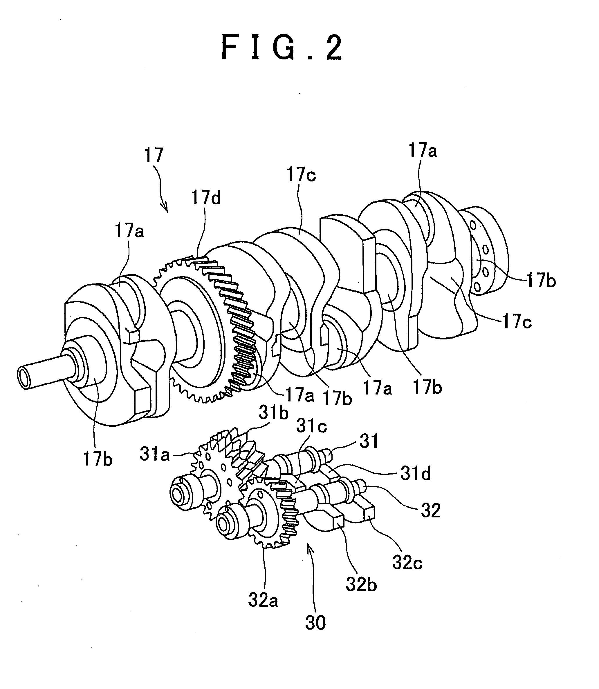
[0030]Each of the pistons 15 is coupled to a crank pin 17a of a crankshaft 17 via a connecting rod 16. The oil pan 13 for storing oil (engine oil) is mounted to the lower part of the crankcase 12 that houses the crankshaft 17.

[0031]An oil pump 18 is provided in the oil pan 13. The oil pump 18 sucks up the oil that is stored in the oil pan 13 t...


PUM


Abstract

In an engine (internal combustion engine), a crankcase is provided with a fastening area that surrounds the opening and contacts the oil pan, a balance shaft housing is disposed in the crankcase to surround the opening, and four housing side fastening sections are provided to the crankcase to fasten the crankcase and the balance shaft housing. The fastening section of the four housing side fastening sections in a first axial direction side of a balance shaft is disposed on the inside of the fastening area, and the fastening section of the four housing side fastening sections in a second axial direction side of the balance shaft is disposed on the outside of the fastening area.

Description

BACKGROUND OF THE INVENTION[0001]1. Field of the Invention[0002]The present invention relates to an internal combustion engine and, in particular, relates to an internal combustion engine that includes a balance shaft housing that is disposed between a crankcase and an oil pan and provided with a balance shaft in a rotatable manner.[0003]2. Description of Related Art[0004]An internal combustion engine that includes a balance shaft housing disposed between a crankcase and an oil pan has been known (see Japanese Patent Application Publication No. 2012-007691 (JP 2012-007691 A), for example).[0005]Generally, in a multi-cylinder internal combustion engine, when rotational imbalance of a crankshaft is caused by a secondary inertia force that is generated by a vertical reciprocating motion of a piston, this further causes vertical vibration of the internal combustion engine. Accordingly, the internal combustion engine is provided with a balancer device to suppress the vertical vibration.[...

Claims


Application Information

Patent Timeline
IPC IPC(8): F16F15/26
CPCF16F15/267F02B75/06F02F7/0046F16F15/264
Inventor SAKATA, KUNIHIKO
Owner TOYOTA JIDOSHA KK
Features
  • R&D
  • Intellectual Property
  • Life Sciences
  • Materials
  • Tech Scout
  • Unparalleled Data Quality
  • Higher Quality Content
  • 60% Fewer Hallucinations
Learn More