Base station

Active Publication Date: 2018-02-15
NTT DOCOMO INC
View PDF8 Cites 20 Cited by
  • Summary
  • Abstract
  • Description
  • Claims
  • Application Information

AI Technical Summary

Benefits of technology

[0007]In light of the above-stated problems, it is an object of the present invention to provide a mapping scheme of the data flow to the radio bearers in the flow-based QoS control.
[0008]In order to overcome the above problems, one aspect of the present invention relates to a base station, comprising: a data flow reception unit configured to receive a data flow having a flow iden

Problems solved by technology

However, it has not been discussed how to allocate respective data transmitted via the tunnel

Method used


Image

  • Base station
  • Base station
  • Base station

Examples


Embodiment Construction

[0021]Embodiments of the present invention are described in detail below with reference to the drawings.

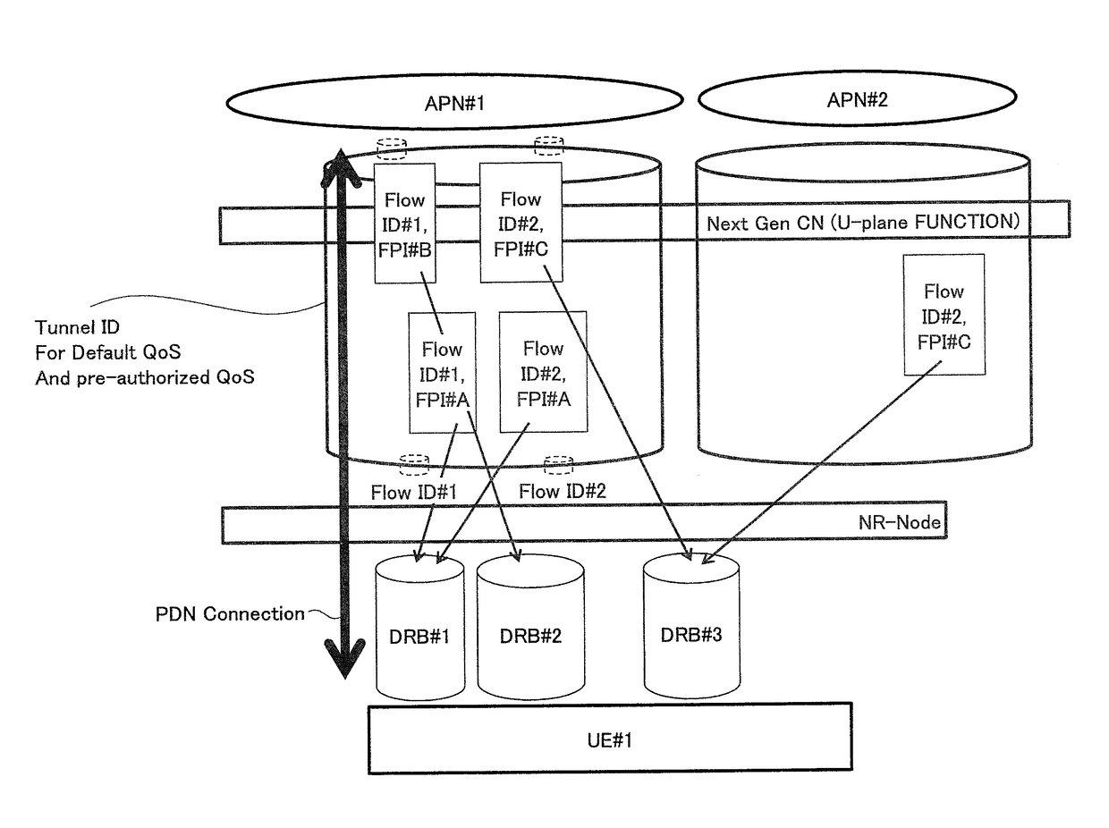
[0022]In the following embodiments, a core network, a base station, and user equipment for implementing flow-based QoS control are disclosed. As a brief overview of embodiments as described later, when receiving a data flow from the core network via a tunnel configured between the core network and the base station, the base station maps the received data flow to radio bearers per flow identifier, per combination of a flow identifier and a flow priority, per flow priority or per tunnel and transmits the data flow to the user equipment through the QoS-controlled radio bearers.

[0023]At the outset, a radio communication system according to one embodiment of the present invention will be described with reference to FIG. 4. FIG. 4 is a schematic diagram illustrating a radio communication system according to one embodiment of the present invention.

[0024]As illustrated in FIG. 4, the radi...


PUM


Abstract

Mapping schemes of data flows to radio bearers in flow-based QoS control are disclosed. One aspect of the present invention relates to a base station including a data flow reception unit configured to receive a data flow having a flow identifier and a flow priority via one or more tunnels and a data flow mapping unit configured to map the received data flow to a radio bearer in accordance with mapping based on one or more of the flow identifier, the flow priority and the tunnels.

Description

BACKGROUND OF THE INVENTION1. Field of the Invention[0001]The present invention relates to a radio communication system.2. Description of the Related Art[0002]In an LTE (Long Term Evolution) system and an LTE-Advanced system, QoS (Quality of Service) control on data is implemented using bearers. As illustrated in FIG. 1, EPS (Evolved Packet System) bearers are configured between user equipment and a PDN GW (Packet Data Network Gateway) in a core network, that is, in an end-to-end. Further, radio bearers (Data Radio Bearers: DRBs) are configured between user equipment and a base station (evolved Node B), an S1-U bearer is configured between the base station and an S-GW (Serving Gateway) in the core network, and an S5 bearer is configured between the S-GW and the PDN GW. Further, the radio bearers, the S1-U bearer, and the S5 bearer are mapped in a one-to-one manner.[0003]Meanwhile, in 3GPP (Third Generation Partnership Project), standardization for next generation (Next Gen) or the f...

Claims


Application Information

Patent Timeline
IPC IPC(8): H04W72/12H04W28/24H04L47/80
CPCH04W72/1242H04L47/805H04L47/24H04W28/24H04W76/12H04W76/11H04W72/569
Inventor HAPSARI, WURI ANDARMAWANTIUCHINO, TOORUTAKAHASHI, HIDEAKIMATSUKAWA, RYUSUKE
Owner NTT DOCOMO INC
Why Eureka
Try Eureka