Vehicle image display system and method

a display system and vehicle technology, applied in the direction of pedestrian/occupant safety arrangement, navigation instruments, instruments, etc., can solve the problems of inability to release or reduce the uneasiness of the occupant, the difficulty of making the occupant recognize the travel state of the own vehicle and other, and the large area of the area. , to achieve the effect of easy recognition

Active Publication Date: 2018-03-01
TAYAMA SHUICHI +1
View PDF9 Cites 46 Cited by
  • Summary
  • Abstract
  • Description
  • Claims
  • Application Information

AI Technical Summary

Benefits of technology

The objective of this patent is to create a car video display system that can show what the car will likely do next while it drives automatically. This way, both the driver and other passengers can quickly and easily see how their car is behaving, making it easier for them to react to any potential issues or risks.

Problems solved by technology

The technical problem addressed in this patent text is how to improve the experience of automated driving of a vehicle by providing information to the occupant about the behavior of the vehicle and the surrounding vehicles in advance, so as to eliminate uneasiness or unpleasantness that may arise during traveling with automated driving. Additionally, the patent text describes various apparatuses and systems for automated driving and parking support, which use different techniques to calculate the shortest route and display the information to the driver in real-time, allowing for safer and more efficient driving.

Method used


Image

  • Vehicle image display system and method
  • Vehicle image display system and method
  • Vehicle image display system and method

Examples


Embodiment Construction

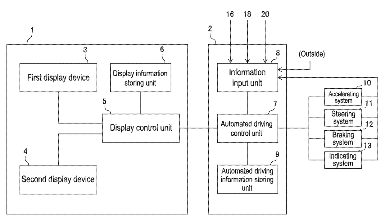
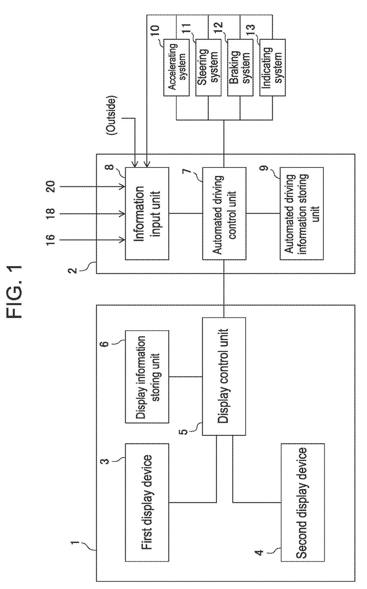
[0056]In Japan, automation degree of automated driving systems for vehicles such as automobiles is defined as being classified into four levels, from Level 1 to Level 4. Level 1 is called a safe driving assisting system with which any of accelerating, steering, and braking is performed by an automobile. Level 2 is called a quasi-automated-driving system with which a plurality of operations among accelerating, steering, and braking is performed by an automobile. Level 3 is also called a quasi-automated-driving system with which all of accelerating, steering, and braking are performed by an automobile while those are performed by a driver only in a case of emergency. Level 4 is called a completely automated driving system with which all of accelerating, steering, and braking are performed something other than a driver completely without involvement of the driver. Here, an automated driving system represents Level 2 through Level 4 (“strategic innovation program (SIP) automated driving...


PUM


Abstract

In a vehicle image display system, a travel behavior of an own vehicle during automated driving to be subsequently performed is previously noticed to an occupant with display to be recognized intuitively and instantaneously. A vehicle image display system includes a first display device that uses a front windshield as a display screen and a second display device as a monitor device mounted on a dashboard, and displays, on a display screen of each display device, a moving image of a virtual image of the own vehicle travelling on an arrow of a symbol image indicating a travel course for lane change as having the arrow as a trajectory therefor so as to visually provide prior notice of the lane change to the occupant when the own vehicle in the automated driving system is about to perform the lane change as being deviated from a scheduled travel course.

Description


Claims


Application Information

Patent Timeline
Owner TAYAMA SHUICHI
Why Eureka
Try Eureka