Unlock instant, AI-driven research and patent intelligence for your innovation.

Image forming apparatus, print control system, and print control method

a technology of image forming apparatus and print control system, which is applied in the direction of digital output to print units, instruments, computing, etc., can solve the problem of inability to efficiently execute two types of jobs

Active Publication Date: 2018-03-01
RICOH KK
View PDF14 Cites 6 Cited by
  • Summary
  • Abstract
  • Description
  • Claims
  • Application Information

AI Technical Summary

Benefits of technology

This patent describes an image forming apparatus that can acquire print job data from a network and execute a print job based on the data. The apparatus has a print manager that sends a request to acquire print job data to a first information processing apparatus, and receives the data in response. The print job receiver then receives additional print job data from a second information processing apparatus. The apparatus can decide to execute the print job based on either the first or second data, or both. The print manager can also obtain information from the print job receiver that indicates whether the second data is being received from the second apparatus. The technical effect of this invention is improved printing efficiency and flexibility that allows for quicker and more efficient printing by obtaining print job data from multiple sources and executing the print job based on that data.

Problems solved by technology

A difficulty arises, however, when the pull printing system is combined with a push printing system, in that the image forming apparatus cannot monitor the progress of such push print jobs, making efficient execution of the two types of job impossible.

Method used


Image

  • Image forming apparatus, print control system, and print control method
  • Image forming apparatus, print control system, and print control method
  • Image forming apparatus, print control system, and print control method

Examples


first embodiment

[0032]A print control system according to a first embodiment is described below with reference to FIGS. 1 to 19.

[0033]FIG. 1 is a diagram illustrating an example of a configuration of a print control system according to the first embodiment of the present disclosure. The print control system of FIG. 1 includes an image forming apparatus 1, a pull printing server 2 (first information processing apparatus), a client terminal 3, push printing servers 4A and 4B (second information processing apparatus), and a network 5.

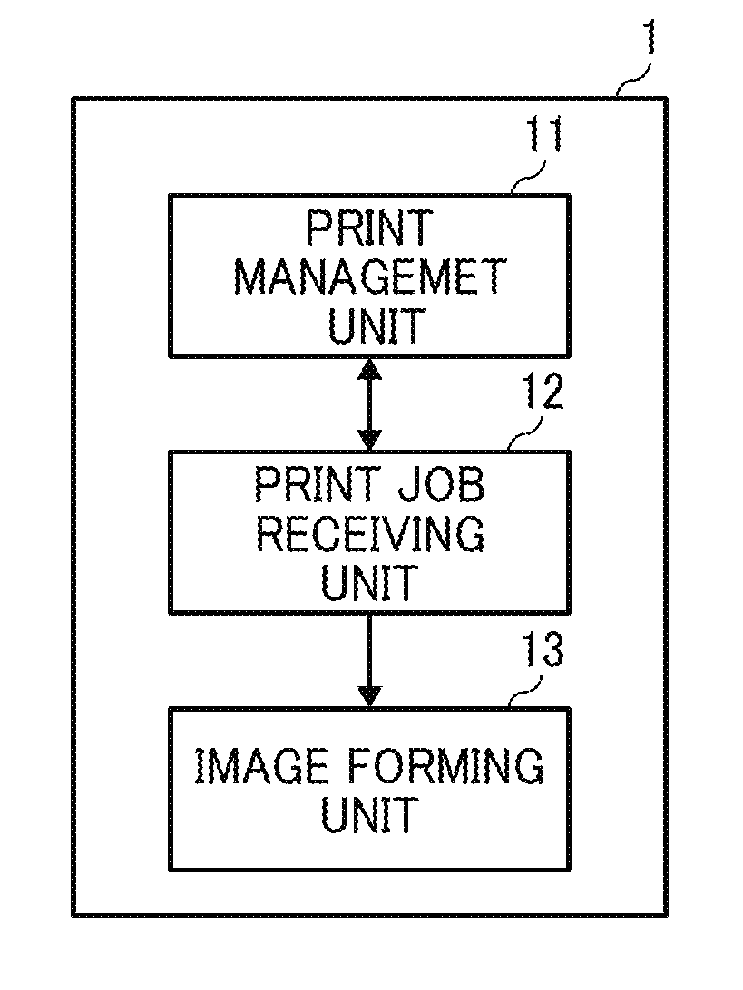
[0034]The image forming apparatus 1 has a printing function, and may be a printer or a multifunction peripheral (MFP) that includes a printer. The image forming apparatus 1 receives print job data from the pull printing server 2 and the push printing servers 4A and 4B, and executes one or more print jobs corresponding to the received print job data.

[0035]The print job data includes print data and print job information. The print data is image data representing an image to...

second embodiment

[0123]A print control system according to a second embodiment of the present disclosure is described below in reference to FIG. 20 and FIG. 21.

[0124]FIG. 20 is a diagram illustrating an example of the print control system according to the second embodiment. As illustrated in FIG. 20, in the print control system according to this embodiment, a function of a pull printing server 2 is provided in a client terminal 3 (first information processing device). Other parts of the configuration of the system according to this embodiment are the same as the print control system according to the first embodiment.

[0125]FIG. 21 is a diagram illustrating an example of a functional configuration of the client terminal 3 according to this embodiment. The client terminal 3 of FIG. 21 includes a print job generating unit 31, a print job transmission unit (first print job transmission unit) 32, and the pull printing server 2. Each component has the same configuration as the first embodiment. The client ...

third embodiment

[0128]A print control system according to a third embodiment of the present disclosure is described below in reference to FIG. 22 and FIG. 23. In the third embodiment, a pull printing server (print control device) 2 serves as a quasi-image forming apparatus. A configuration of each component of the print control system according to this embodiment is the same as the print control system according to the first embodiment.

[0129]FIG. 22 is a flowchart of an example process of executing a print job by an image forming apparatus 1 according to the third embodiment. The processing of S401 to S411 in FIG. 22 is the same as that in FIG. 17.

[0130]As described in FIG. 22, when the print management unit 11 selects a print job registered in the push printing server 4 (S402: NO), the print management unit 11 sends a print job start request to the pull printing server 2 (S411). As described above, the print job start request includes an address and an apparatus ID of the image forming apparatus 1...


PUM


Abstract

An image forming apparatus includes a print manager to send a print job acquisition request that requests acquisition of print job data to a first information processing apparatus through a network, and receive first print job data sent from the first information processing apparatus as a response to the print job acquisition request through the network, a print job receiver to receive the first print job data sent from the print manager, and second print job data sent from a second information processing apparatus via the network, and an image forming device to execute a print job corresponding at least one of the first print job data and the second print job data, which are received from the print job receiver. The print manager obtains, from the print job receiver, information indicating whether the second print job data is being received from the second information processing apparatus.

Description

CROSS-REFERENCE TO RELATED APPLICATION[0001]This patent application is based on and claims priority pursuant to 35 U.S.C. §119(a) to Japanese Patent Application No. 2016-166206, filed on Aug. 26, 2016, in the Japan Patent Office, the entire disclosure of which is hereby incorporated by reference herein.BACKGROUNDTechnical Field[0002]The embodiments of present disclosure relate to an image forming apparatus, a print control system, and a print control method.Related Art[0003]A pull printing system including an image forming apparatus and a print server to provide a printing function using a pull method is known. The image forming apparatus sends a request to the print server for acquiring print job data according to a user instruction and executes one or more print jobs corresponding to the print job data received as a response to the acquisition request. Such an image forming apparatus can efficiently execute a plurality of print jobs in a desired order by monitoring the progress of...

Claims


Application Information

Patent Timeline
IPC IPC(8): G06F3/12H04N1/00H04N1/23
CPCG06F3/1259H04N1/00954H04N2201/0094H04N1/2315H04N2201/0039G06F3/1205G06F3/1203G06F3/1212G06F3/1261G06F3/1263G06F3/1288
Inventor WATANABE, HODAKA
Owner RICOH KK