
Method and device for electronically controlling a vehicle deceleration in an abs braking system

Active Publication Date: 2018-03-15
ZF CV SYST EURO BV
View PDF0 Cites 12 Cited by
  • Summary
  • Abstract
  • Description
  • Claims
  • Application Information

AI Technical Summary

Benefits of technology

The patent text describes a method for controlling the brakes of a vehicle to prevent excessive wear and improve safety and comfort. The method takes into account factors such as the vehicle's speed and the amount of braking force applied to determine the appropriate amount of brake pressure. By adjusting the differential slip between the vehicle's axles, the method helps to calm down the vehicle's deceleration and reduce the likelihood of premature engagement of the vehicle's brakes. This results in a safer and more comfortable driving experience.

Problems solved by technology

In this case, the brake pressure at the wheel brakes of the rear wheels is limited if the actual differential slip exceeds a setpoint differential slip.
The disadvantage in this case is that an increase of the setpoint differential slip at a high vehicle setpoint deceleration effectuates an early activation of the ABS control, whereby the braking behavior becomes less calm and less safe, since the ABS control must engage sooner.
The disadvantage in this case is that, above the maximum deceleration, the braking behavior is turbulent overall, due to the tracking, and is perceived as unpleasant.
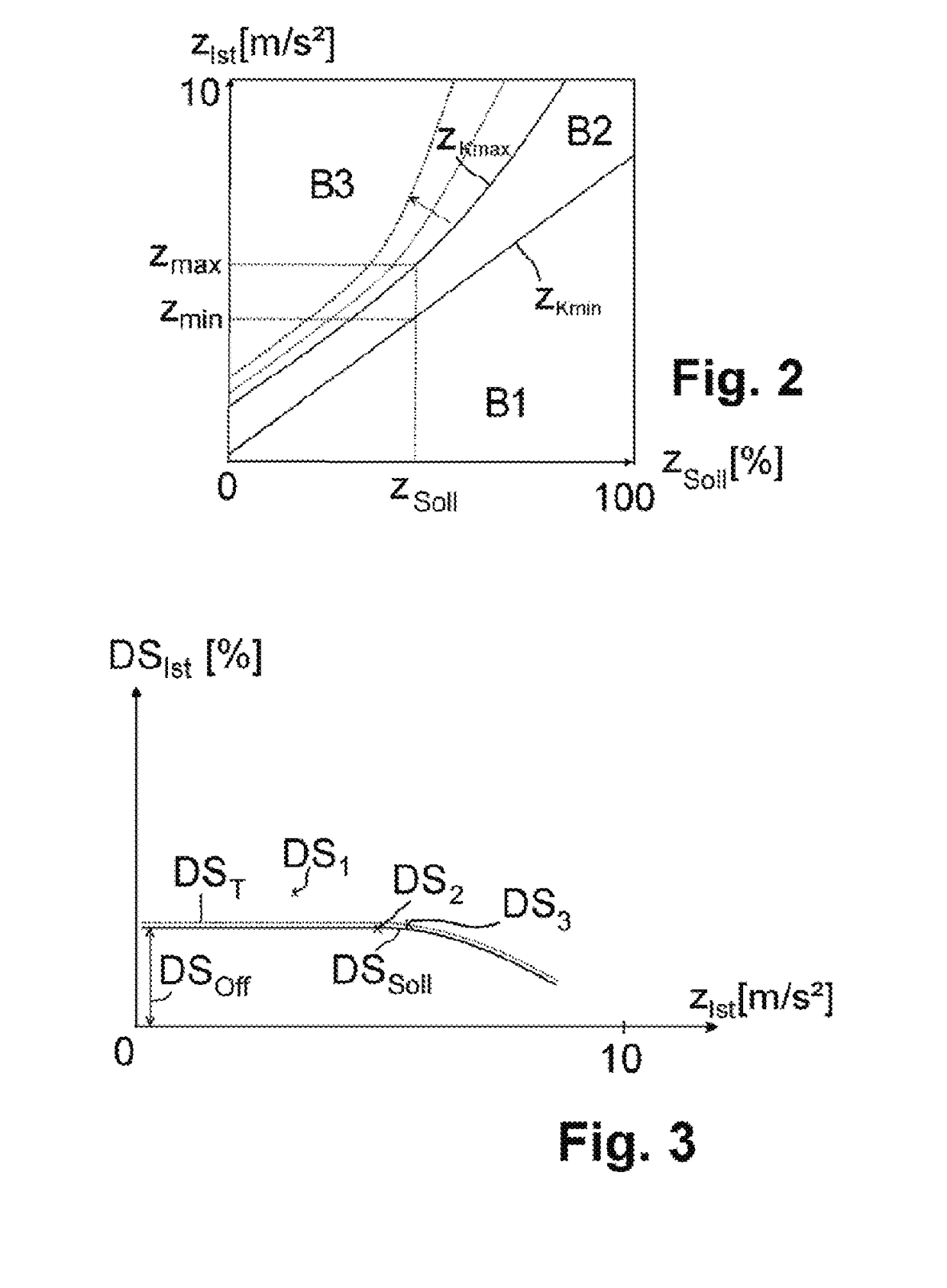
Therefore, the rear axle brake pressure is already limited at a lower actual differential slip, i.e. at a lower relative over-braking, due to the setpoint differential slip which decreases as the actual vehicle deceleration or the setpoint vehicle deceleration increases.
If the actual differential slip is less than the setpoint differential slip, however, the front axle is over-braked relative to the rear axle, i.e. the rear axle brake pressure is limited.

Method used


Image

  • Method and device for electronically controlling a vehicle deceleration in an abs braking system
  • Method and device for electronically controlling a vehicle deceleration in an abs braking system
  • Method and device for electronically controlling a vehicle deceleration in an abs braking system

Examples


Embodiment Construction

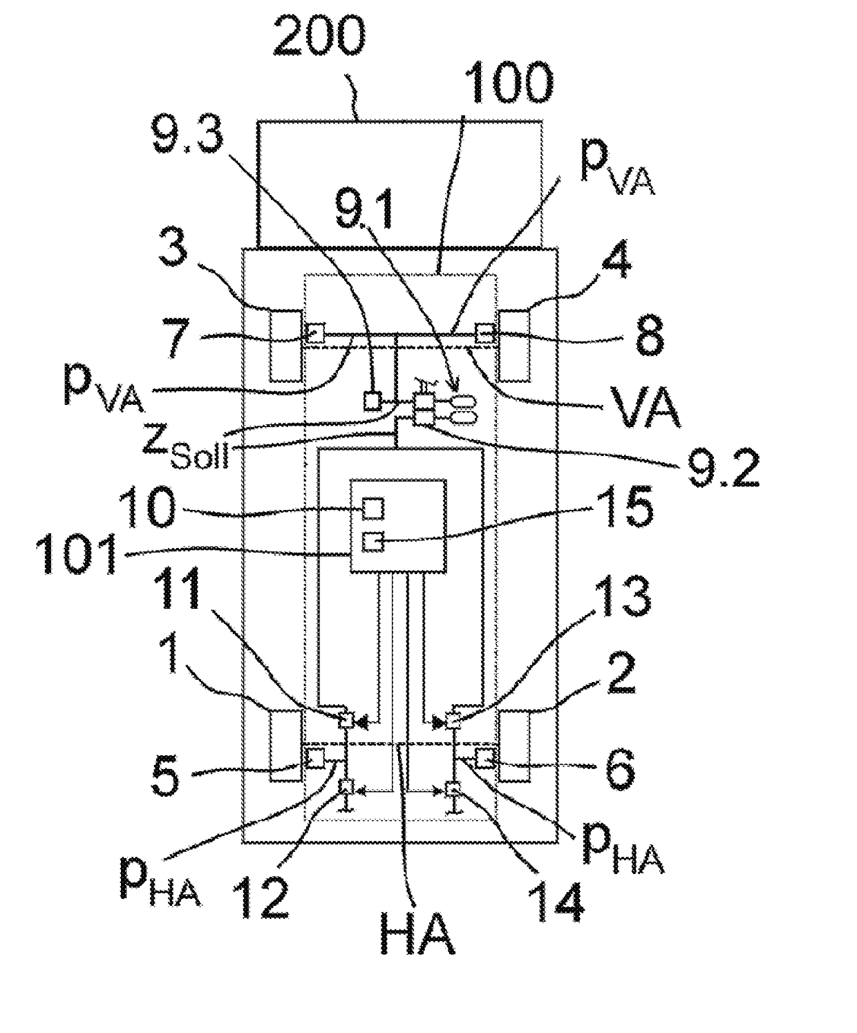
[0018]Embodiments of the present invention provide methods and devices for electronically controlling a vehicle deceleration in an ABS braking system that ensure a pleasant and safe braking process having a steady braking behavior.

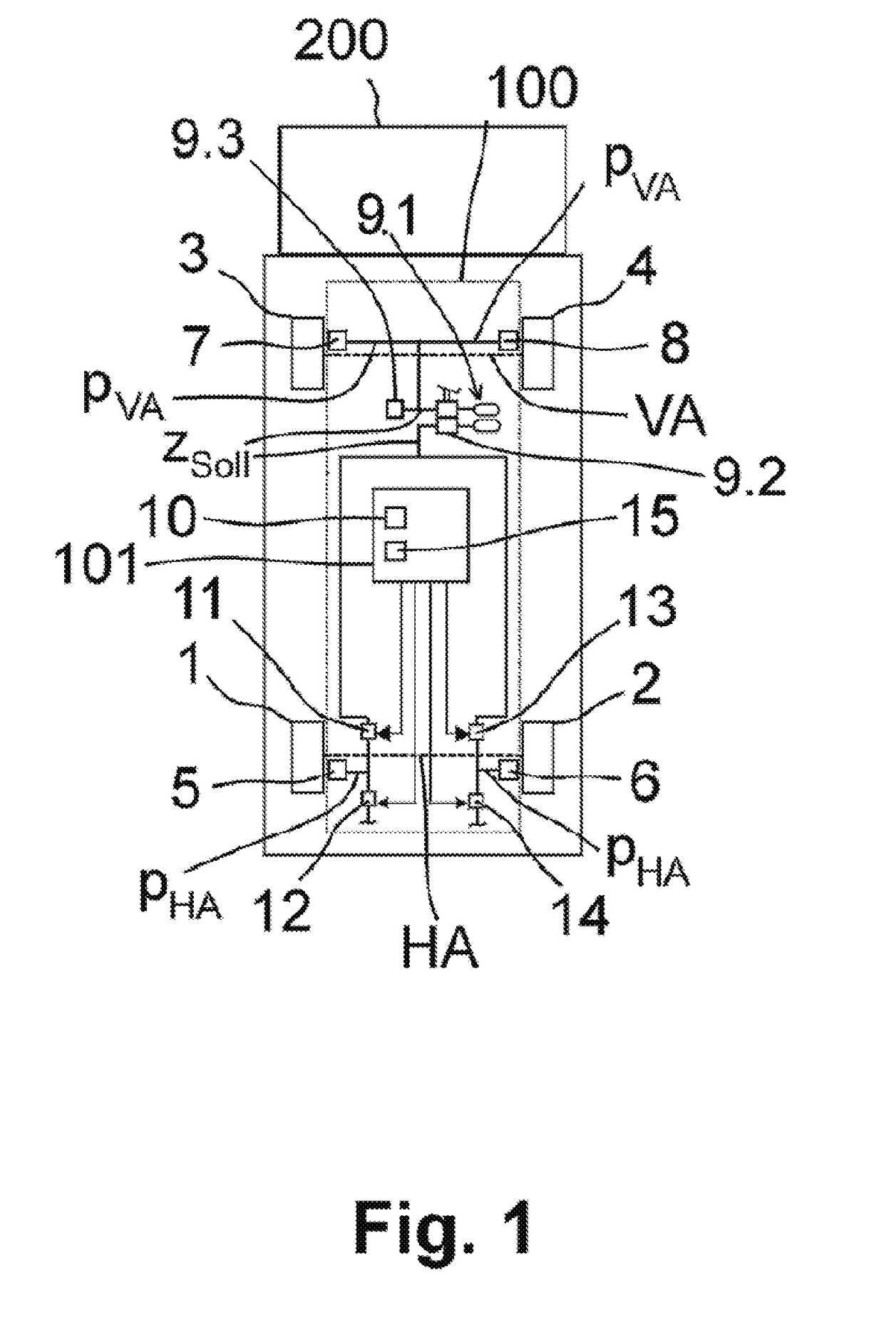
[0019]According to embodiments of the invention a brake pressure at wheel brakes of a vehicle axle is controlled as a function of a detected actual vehicle deceleration, i.e. a negative actual acceleration of the vehicle, wherein the brake pressure at the wheel brakes of this vehicle axle is limited when the actual vehicle deceleration is greater than a maximum deceleration, and the brake pressure is increased at the wheel brakes of this vehicle axle when the actual vehicle deceleration is less than a minimum deceleration. In this case, “limit” is understood to mean that the brake pressure at the wheel brakes of the vehicle axle to be controlled must not be further increased, i.e., the brake pressure can only be held at the present value or, depending on a...


PUM


Abstract

A method for controlling a vehicle deceleration in a vehicle comprising an ABS braking system includes detecting a setpoint vehicle deceleration predetermined by a driver; establishing a maximum deceleration and a minimum deceleration, in each case as a function of the detected setpoint vehicle deceleration; detecting an actual vehicle deceleration; and controlling a brake pressure at wheel brakes of a vehicle axle to be controlled as a function of the detected actual vehicle deceleration by controlling ABS brake valves. Controlling the brake pressure at the wheel brakes of the vehicle axle as a function of the detected actual vehicle deceleration comprises: increasing the brake pressure at the wheel brakes when the actual vehicle deceleration is less than the minimum deceleration, and limiting the brake pressure at the wheel brakes when the actual vehicle deceleration is greater than the maximum deceleration.

Description

CROSS REFERENCE TO RELATED APPLICATIONS[0001]This application is a U.S. National Stage Application under 35 U.S.C. § 371 of International Application No. PCT / EP2016 / 000667 filed on Feb. 26, 2016, and claims benefit to German Patent Application No. DE 10 2015 006 738.9 filed on May 23, 2015. The International Application was published in German on Dec. 1, 2016 as WO 2016 / 188602 A1 under PCT Article 21(2).FIELD[0002]The invention relates to a method for electronically controlling a vehicle deceleration in an ABS braking system, in particular in a commercial vehicle, by adjusting the brake pressure at a vehicle axle to be controlled as a function of a present actual vehicle deceleration, and to a device for carrying out the method.BACKGROUND[0003]In commercial vehicles, brake pressure control which limits the brake pressure (electronic brake force limiter, EBL) is used, in particular, for distributing the braking effect desired by a braking system or a driver to the vehicle axles in a ...

Claims


Application Information

Patent Timeline
IPC IPC(8): B60T8/1766B60T8/1761B60T8/32B60T8/34
CPCB60T8/1766B60T8/1761B60T8/321B60T8/341B60T8/176B60T8/1708
Inventor BOETHEL, ANDREASECKERT, HORSTWALLBAUM, TORSTEN
Owner ZF CV SYST EURO BV
Learn More