
Providing memory bandwidth compression using adaptive compression in central processing unit (CPU)-based systems

a technology of memory bandwidth and adaptive compression, applied in the direction of memory address/allocation/relocation, instruments, climate sustainability, etc., can solve the problems of reducing the performance of the cpu-based system, limiting the memory bandwidth, and increasing the latency of memory accesses

Active Publication Date: 2018-03-15
QUALCOMM INC
View PDF5 Cites 13 Cited by
  • Summary
  • Abstract
  • Description
  • Claims
  • Application Information

AI Technical Summary

Benefits of technology

This patent describes a system and method for compressing memory bandwidth in CPU-based systems. The system includes a compressed memory controller (CMC) and a system cache that work together to compress memory lines into groups of associated memory lines. The CMC uses two compression mechanisms to compress small and large amounts of data. The system cache provides a prefetch accuracy indicator to determine which memory lines should be read. The method involves receiving a memory write request, compressing each memory line separately, and determining if the second compression result is smaller than the first. The system then stores the second compression result in the compressed data area if it is smaller. This technology helps improve memory bandwidth utilization and performance in CPU-based systems.

Problems solved by technology

As CPU-based applications executing in the CPU-based system 102 in FIG. 1 increase in complexity and performance, limitations on memory bandwidth may impose a constraint on the CPU-based system 102.
Such queueing of memory access requests may increase the latency of memory accesses, which in turn may decrease the performance of the CPU-based system 102.
While increasing the memory line size of the CPU-based system 102 may result in higher data compression ratios in some circumstances, an increased memory line size may also cause an increase in wasted memory bandwidth.

Method used


Image

  • Providing memory bandwidth compression using adaptive compression in central processing unit (CPU)-based systems
  • Providing memory bandwidth compression using adaptive compression in central processing unit (CPU)-based systems
  • Providing memory bandwidth compression using adaptive compression in central processing unit (CPU)-based systems

Examples


Embodiment Construction

[0018]With reference now to the drawing figures, several exemplary aspects of the present disclosure are described. The word “exemplary” is used herein to mean “serving as an example, instance, or illustration.” Any aspect described herein as “exemplary” is not necessarily to be construed as preferred or advantageous over other aspects.

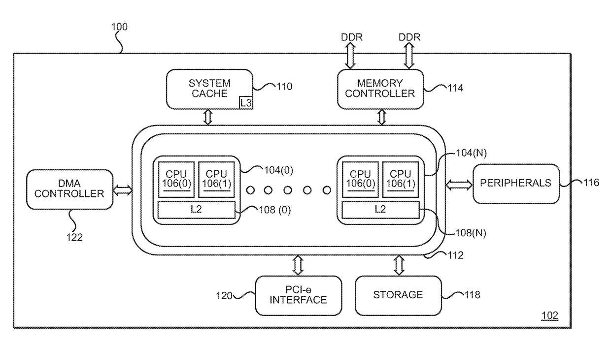
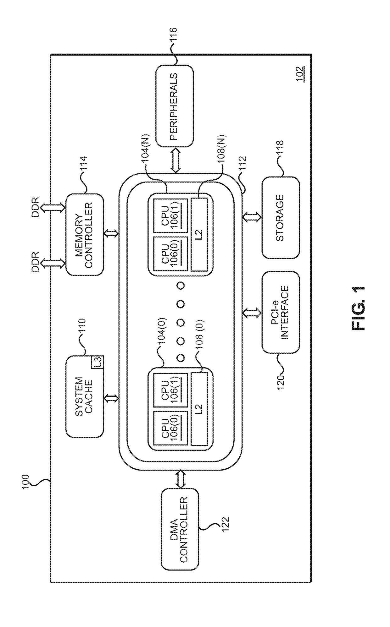
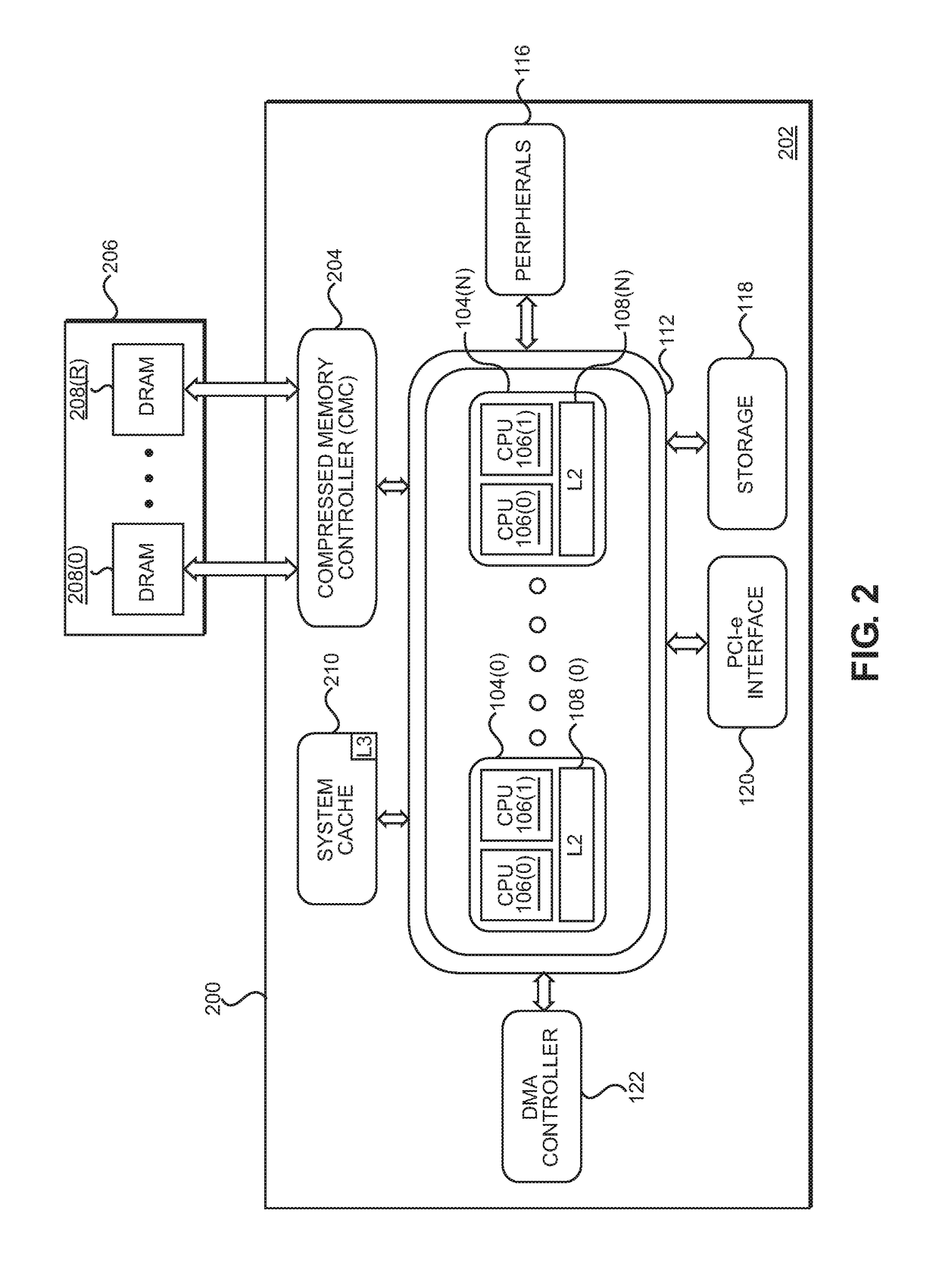
[0019]Aspects disclosed herein include providing memory bandwidth compression using adaptive compression in central processing unit (CPU)-based systems. In some aspects, a compressed memory controller (CMC) is configured to provide adaptive memory bandwidth compression by decompressing memory read requests and / or compressing memory write requests. As used herein, “adaptive compression” refers to compressing and decompressing multiple memory lines either separately using a first compression mechanism or together using a second compression mechanism, depending on which approach provides a greater compression ratio and / or depending on a determined effect...


PUM


Abstract

Providing memory bandwidth compression using adaptive compression in central processing unit (CPU)-based systems is disclosed. In one aspect, a compressed memory controller (CMC) is configured to implement two compression mechanisms: a first compression mechanism for compressing small amounts of data (e.g., a single memory line), and a second compression mechanism for compressing large amounts of data (e.g., multiple associated memory lines). When performing a memory write operation using write data that includes multiple associated memory lines, the CMC compresses each of the memory lines separately using the first compression mechanism, and also compresses the memory lines together using the second compression mechanism. If the result of the second compression is smaller than the result of the first compression, the CMC stores the second compression result in the system memory. Otherwise, the first compression result is stored.

Description

BACKGROUNDI. Field of the Disclosure[0001]The technology of the disclosure relates generally to computer memory systems, and, in particular, to memory controllers in computer memory systems for providing central processing units (CPUs) with a memory access interface to memory.II. Background[0002]Microprocessors perform computational tasks for a wide variety of applications. A typical microprocessor application includes one or more central processing units (CPUs) that execute software instructions. The software instructions may instruct a CPU to fetch data from a location in memory, perform one or more CPU operations using the fetched data, and generate a result. The result may then be stored in memory. As non-limiting examples, this memory can be a cache local to the CPU, a shared local cache among CPUs in a CPU block, a shared cache among multiple CPU blocks, or main memory of the microprocessor.[0003]In this regard, FIG. 1 is a schematic diagram of an exemplary system-on-a-chip (S...

Claims


Application Information

Patent Timeline
Patent Type & Authority Applications(United States)
IPC IPC(8): G06F12/02
CPCG06F12/023G06F2212/608G06F2212/401G06F2212/1044G06F12/0804G06F12/0866G06F12/0875G06F2212/1024G06F2212/502Y02D10/00H04L47/38H04L69/04
Inventor VERRILLI, COLIN BEATONVAIDHYANATHAN, NATARAJANHEDDES, MATTHEUS CORNELIS ANTONIUS ADRIANUS
Owner QUALCOMM INC
Learn More