Seat support apparatus

a technology for supporting devices and seats, applied in the direction of chairs, vehicle components, vehicle arrangements, etc., to achieve the effect of reducing the resilient force of elastic members

Inactive Publication Date: 2018-03-22
AISIN SEIKI KK
View PDF0 Cites 1 Cited by
  • Summary
  • Abstract
  • Description
  • Claims
  • Application Information

AI Technical Summary

Benefits of technology

[0004]However, when external force acts on the movable member in a direction in which the airbag deploys (for example, when vehicle occupant pulls movable member), the seat support device of patent document 1 can move the movable member in a limitless manner against the biasing force of the elastic member. This may, for example, reduce the resilient force of the elastic member or separate the movable member.

Problems solved by technology

However, when external force acts on the movable member in a direction in which the airbag deploys (for example, when vehicle occupant pulls movable member), the seat support device of patent document 1 can move the movable member in a limitless manner against the biasing force of the elastic member.

Method used


Image

  • Seat support apparatus
  • Seat support apparatus
  • Seat support apparatus

Examples


Embodiment Construction

[0019]One embodiment of a seat support device will now be described.

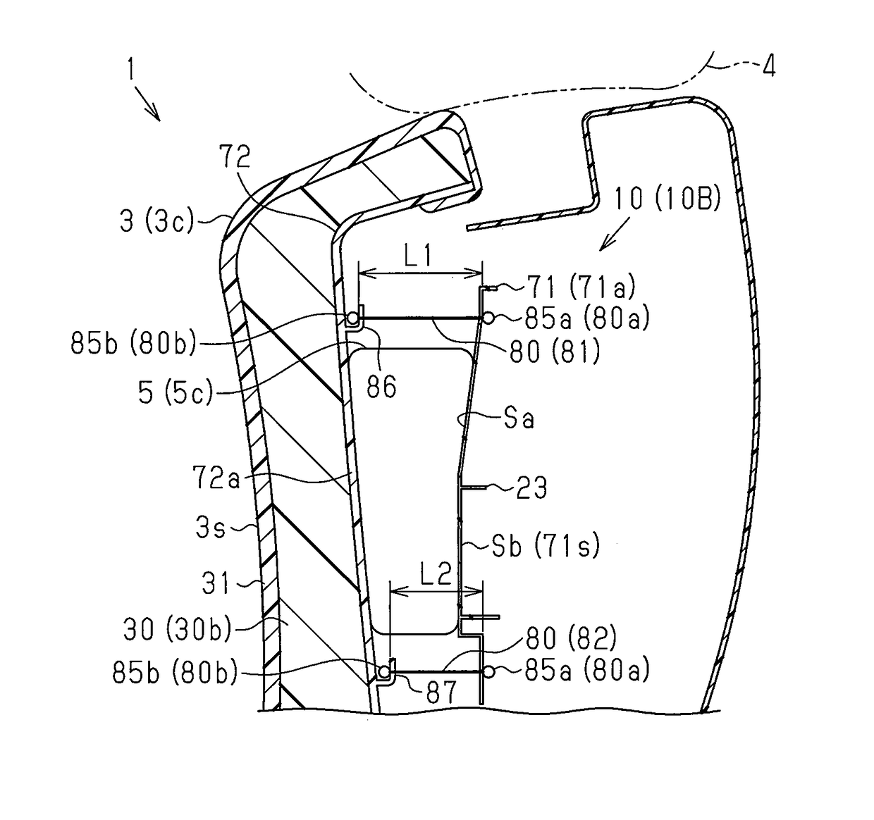
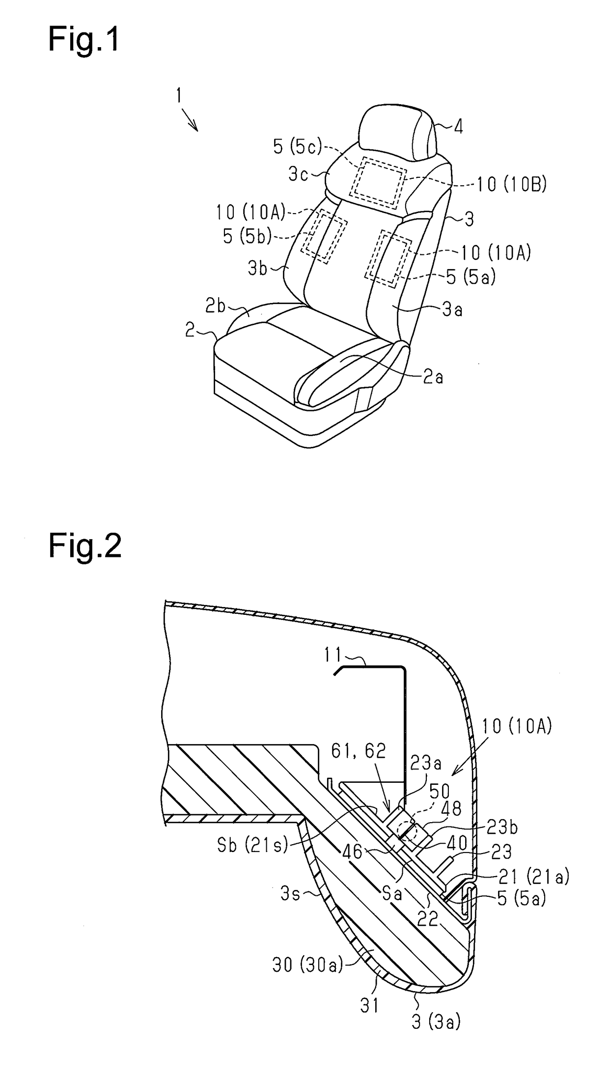
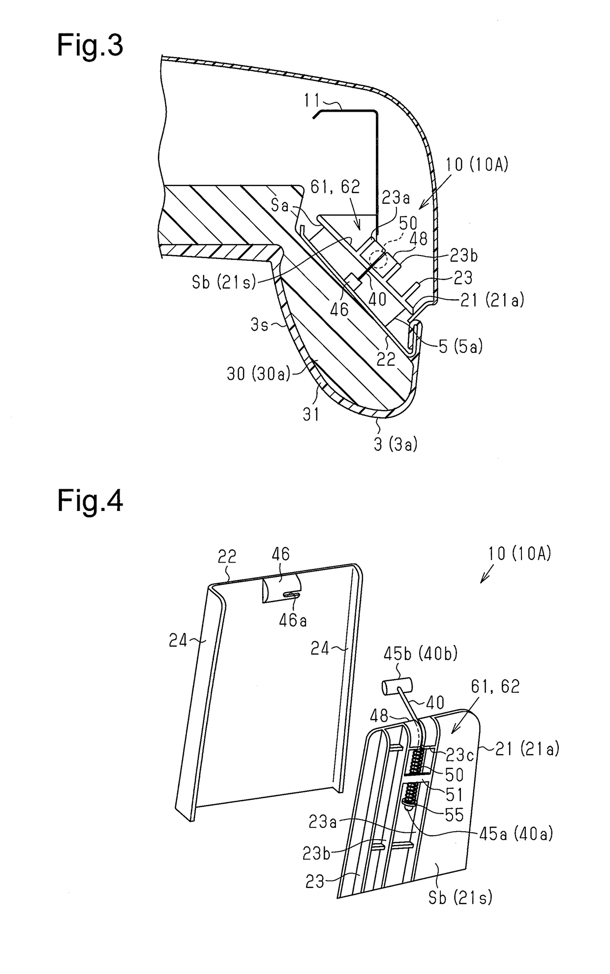
[0020]As shown in FIG. 1, a vehicle seat 1 includes a seat cushion 2, a seat back 3 arranged at a rear end of the seat cushion 2 in an inclinable manner, and a head rest 4 arranged at an upper end of the seat back 3. A plurality of seat support devices 10 (10A, 10B) are arranged in the seat back 3.

[0021]Further, the seat back 3 includes seat back side portions 3a and 3b and a seat back shoulder portion 3c, each having a frontward bulging support shape. This ensures a satisfactory seating position for the vehicle occupant who is seated on the seat 1 and kept at the seating position.

[0022]Each of the support devices 10 (10A, 10B) includes an airbag 5 (5a to 5c) arranged inside the seat back 3. An air supply / discharge device (not shown) charges the airbag 5 with air and discharges air from the airbags 5 to expand and contract the airbags 5. This allows the seat support devices (10A, 10B) to change the support shapes se...


PUM


Abstract

A seat support device includes a base, a paddle, an airbag, and a cable. The base is fixed to an inner side of a seat. The paddle is movable toward and away from the base. The airbag is arranged between the base and the paddle. The airbag pushes a seat pad of the seat with the paddle when deployed. The cable includes a first end engaged with the base and a second end engaged with the paddle.

Description

TECHNICAL FIELD[0001]The present invention relates to a seat support device.BACKGROUND ART[0002]A pneumatic seat support device can change a support shape of a seat by deploying an airbag, which is arranged inside the seat, to push a seat pad. Further, such a seat support device usually includes a movable member that is moved by the expansion and contraction of the airbag, a fixed member, and an elastic member arranged between the movable member and the fixed member. Patent document 1 describes an example of a seat support device including a helical extension spring arranged between the movable member and the fixed member. When the airbag contracts, the elastic force of the helical extension spring returns the movable member to its initial position.PRIOR ART DOCUMENTPatent Document[0003]Patent Document 1: Japanese National Phase Laid-Open Patent Publication No. 2008-541896SUMMARY OF THE INVENTIONProblems that are to be Solved by the Invention[0004]However, when external force acts o...

Claims


Application Information

Patent Timeline
Patent Type & Authority Applications(United States)
IPC IPC(8): B60N2/44A47C7/14A47C7/40
CPCB60N2/4415B60N2/22B60N2/914A47C7/14A47C7/40B60N2/2222B60N2/99
Inventor HASHIMOTO, KENJIMORI, MASATOSHI
Owner AISIN SEIKI KK
Why Eureka
Try Eureka