External vacuum sealer

a vacuum sealer and vacuum technology, applied in the field of vacuum sealing technique, can solve the problems of inconvenient use, high cost, inconvenient use, low vacuum or non-vacuum in the vacuum bag, etc., and achieve the effect of improving production efficiency and quality, and ensuring the airtightness of the plastic bag

Active Publication Date: 2018-03-22
BIGLAND ELECTRIC APPLIANCE
View PDF2 Cites 8 Cited by
  • Summary
  • Abstract
  • Description
  • Claims
  • Application Information

AI Technical Summary

Benefits of technology

[0006]An aspect relates to an external vacuum sealer, wherein a heating band can be moved up or down, in order to control the heating band being closed to or far from the heat adhesive strip. The vacuum sealer ensures the vacuum of a plastic bag, and improves the production efficiency.
[0018]The present invention provides a lifting mechanism which is able to drive the heating band assembly up and down, that is, when the plastic bag need to be sealed, the heating band assembly approaches the heating adhesive strip until the plastic bag is compressed and sealed; in the meantime, the heating band assembly can be far from the heating adhesive strip and the plastic bag, thereby the air is evacuated from the plastic bag completely. The present invention is able to avoid a problem that the plastic bag is sealed somewhere during vacuuming, due to the residual heat of the heating band assembly. Therefore, the present invention ensures airtightness of the plastic bag, and improves the production efficiency and quality.

Problems solved by technology

However if the vacuum sealer is used consecutively for a long time, the heating band will have high temperature, causing the plastic bag being sealed before vacuumed whereby leading to a low-vacuum or non-vacuum therein.
One of the solutions to the above defect is to prolong an interval between two operations so as to cool the heating band, however it requires a long time to wait with inconvenience.
Another solution is to use a fan blowing on the heating band, but this solution requires a complex structure and a little long time while the cooling effect is not good, with more costs and inconvenient use.

Method used


Image

  • External vacuum sealer
  • External vacuum sealer
  • External vacuum sealer

Examples


Embodiment Construction

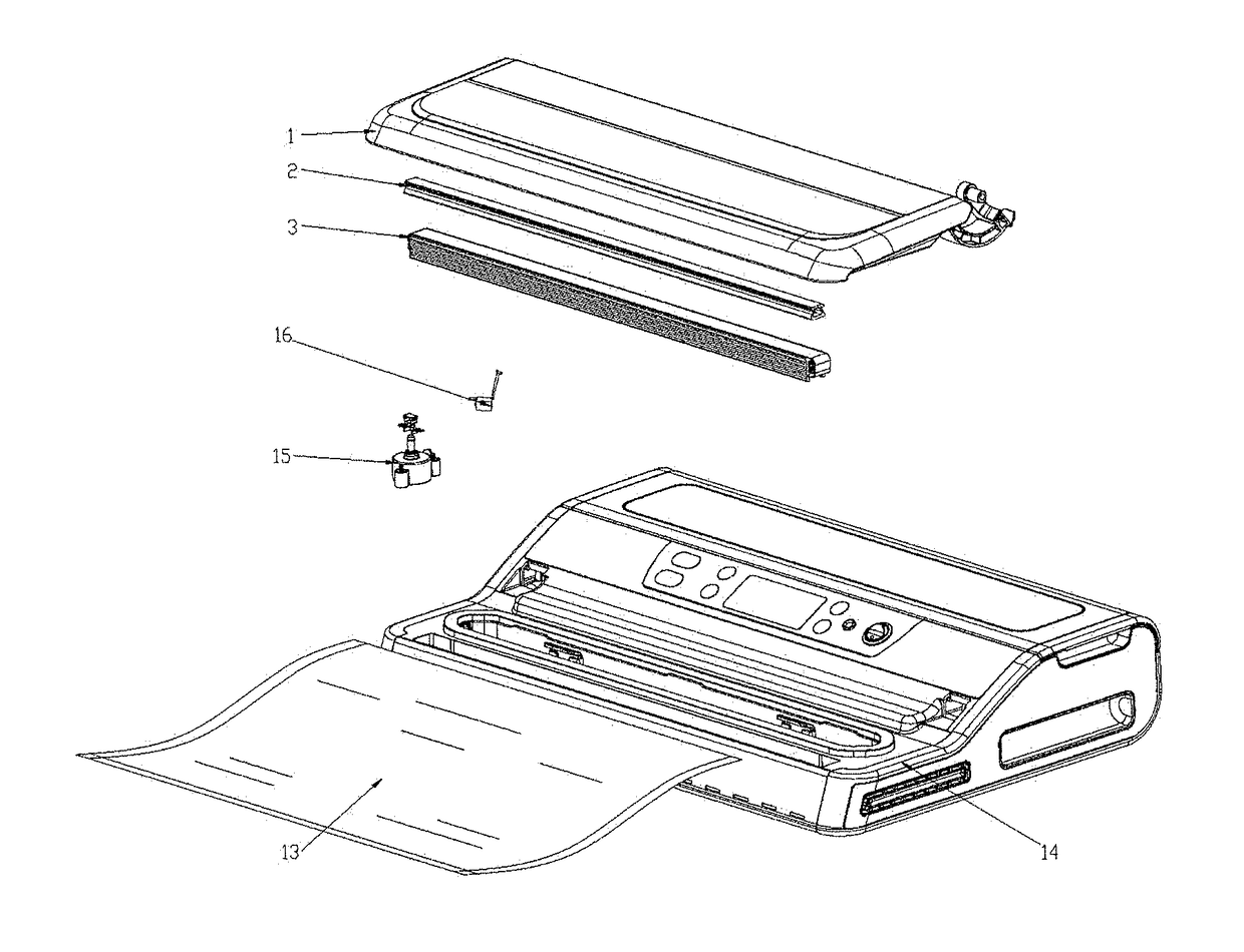
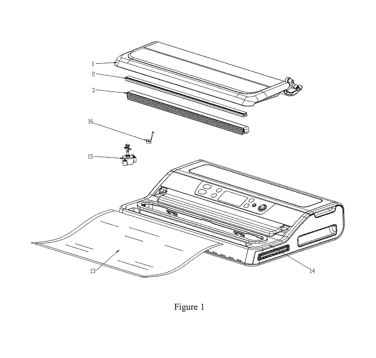
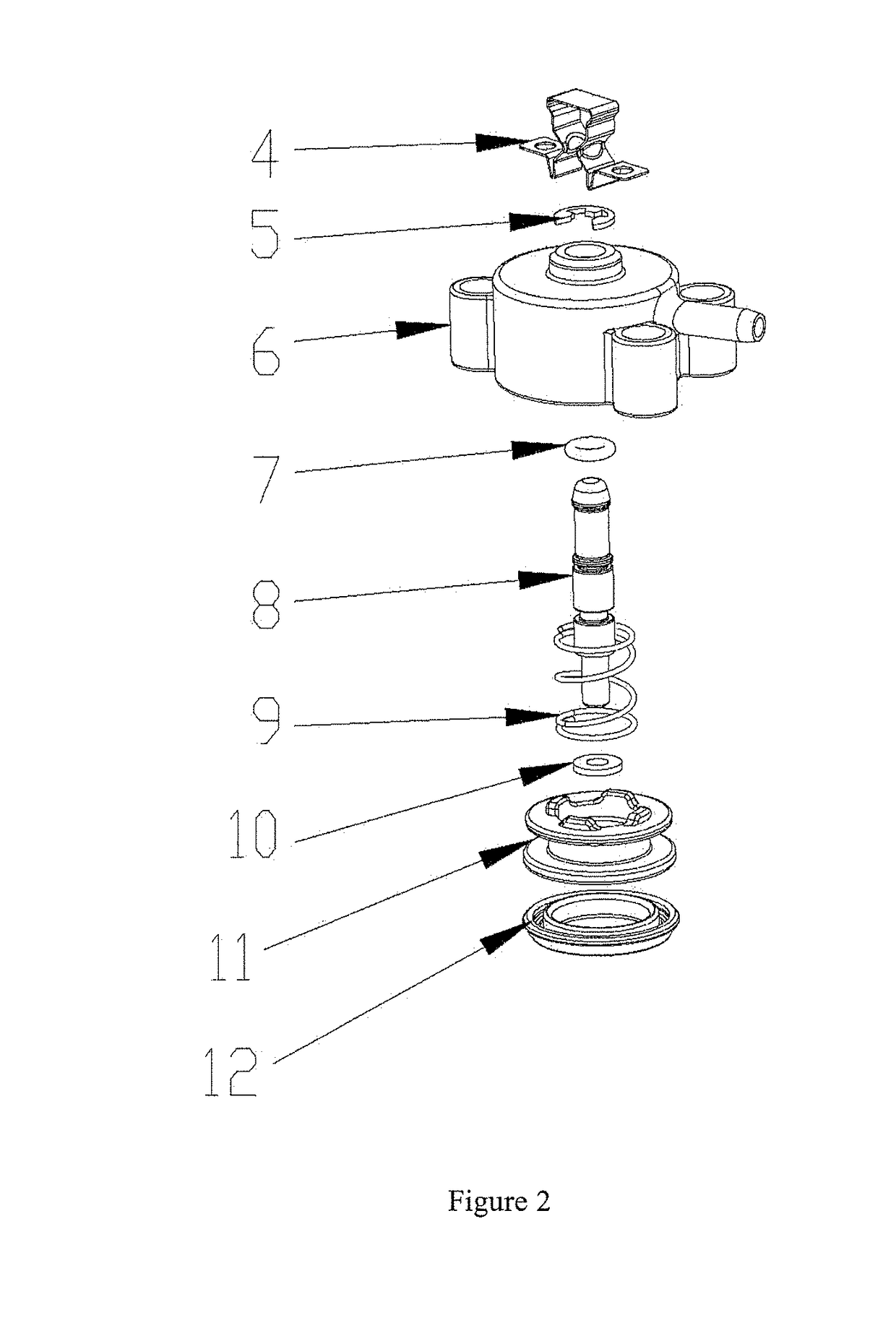
[0025]In order to facilitate the skilled person in the art understanding embodiment of the present invention, the invention will be further described with reference to the accompanying drawing.

[0026]As shown in FIG. 1-6, an external vacuum sealer, according to embodiment of the present invention, comprises a case, a heating adhesive strip 2, a heating band assembly 3 and a lifting mechanism that all are installed in the case. The heating band assembly 3 is set up underneath the heating adhesive strip 2, and is attached to the lifting mechanism. A plastic bag 13 is disposed between the heating adhesive strip 2 and the heating band assembly 3. The lifting mechanism is able to drive the heating band assembly 3 up such that the heating band assembly 3 approaches the heating adhesive strip 2 until the plastic bag 13 is compressed and sealed. On the contrary, the lifting mechanism can also drives the heating band assembly 3 down such that the heating band assembly 3 will be far from the h...


PUM


Abstract

The present invention discloses an external vacuum sealer comprising a case, a heating adhesive strip, a heating band assembly and a lifting mechanism that all are installed in the case. The heating band assembly is set up underneath the heating adhesive strip, and is attached to the lifting mechanism. A plastic bag is disposed between the heating adhesive strip and the heating band assembly; the lifting device is able to drive the heating band assembly up such that the heating band assembly approaches the heating adhesive strip until the plastic bag is compressed and sealed; the lifting mechanism is also able to drive the heating band assembly down such that the heating band assembly can be far from the heating adhesive strip and the plastic bag. The lifting mechanism includes a pump unit that connects to the air pipe via the magnetic valve. The present invention enhances the production efficiency.

Description

CROSS REFERENCE TO RELATED APPLICATION[0001]This application claims priority of Application No. 201610837154.5 filed in China on Sep. 21, 2016, under 35 U.S.C. § 119, the entire contents of which are hereby incorporated by reference.TECHNICAL FIELD[0002]The present invention relates to a field of vacuum sealing technique, in particular to an external vacuum sealer.BACKGROUND[0003]Vacuum sealer is being used widely in daily life, and there high demand on the number of consecutive use thereto.[0004]Conventional vacuum sealer works in such manner that, an open end of plastic bag is placed between a heating band and a heat adhesive strip in the vacuum sealer, then compressed, vacuumed and sealed. However if the vacuum sealer is used consecutively for a long time, the heating band will have high temperature, causing the plastic bag being sealed before vacuumed whereby leading to a low-vacuum or non-vacuum therein.[0005]One of the solutions to the above defect is to prolong an interval be...

Claims


Application Information

Patent Timeline
Patent Type & Authority Applications(United States)
IPC IPC(8): B65B31/02
CPCB65B31/024B65B31/06B65B51/10B65B51/146B65B31/048
Inventor HU, ZHIHEZHENG, XINZHAICHEN, JIONGXIAN
Owner BIGLAND ELECTRIC APPLIANCE
Why Eureka
Try Eureka