Deterioration detector for non-aqueous electrolyte power storage element, power storage device, deterioration detection system for non-aqueous electrolyte power storage element, and deterioration detection method for non-aqueous electrolyte power storage element

Active Publication Date: 2018-03-22
GS YUASA INT LTD
2 Cites 1 Cited by

AI-Extracted Technical Summary

Problems solved by technology

Then, it become difficult for the lithium ions to be diffused in the positive electrode after repeated charging and discharging to the non-aqueous electrolyte power storage element, the region in which no contribution to charging and discharging i...

Method used

[0037]By the simple configuration of comparing the predetermined threshold with the ratio of or the difference between the first increase rate and the second increase rate, it is possible to detect deterioration of the non-aqueous electrolyte power storage element reliably and easily.
[0040]The higher the SOC when the direct current resistance values are measured is, the more noticeable the difference between the first increase rate and the second increase rate. Therefore, like in the above configuration, by measuring the direct current resistance values when the non-aqueous electrolyte power storage element is charged until the high SOC state (the SOC is 50% or higher and 100% or lower), deterioration of the power storage element may be detected more reliably.
[0043]In this manner, by making the SOC of the non-aqueous electrolyte power storage element 100%, potential gradient may be applied to the positive active material as a whole. Therefore, it is possible to reduce a region in which no contribution to charging and discharging is made that has expanded in the positive electrode. With this, deterioration of the non-aqueous electrolyte power storage element (charge-discharge performance) may be recovered.
[0044]In this case, by the charging unit charging the non-aqueous electrolyte power storage element up to the point at which the SOC reaches 100%, and then performing the charge for a predetermined time period, the region in which no contribution to charging and discharging is made in the positive electrode is reduced further. Therefore, it is possible to recover deterioration of the non-aqueous electrolyte power storage element (charge-dis...

Benefits of technology

[0010]the control unit detects deterioration of a non-aqueous electrolyte power storage element based on a first increase rate and a second increase rate, the first increase rate being an increase rate of a direct current resistance value obtained by measuring the non-aqueous elec...

Abstract

According to an embodiment of the present invention, deterioration of a non-aqueous electrolyte power storage element is detected based on a first increase rate and a second increase rate, the first increase rate being an increase rate of a direct current resistance value obtained by measuring the non-aqueous electrolyte power storage element over a first time period, the second increase rate being an increase rate of a direct current resistance value obtained by measuring the non-aqueous electrolyte power storage element over a second time period that is longer than the first time period.

Application Domain

Electrical testingCells structural combination +1

Technology Topic

Power storageEngineering +3

Image

  • Deterioration detector for non-aqueous electrolyte power storage element, power storage device, deterioration detection system for non-aqueous electrolyte power storage element, and deterioration detection method for non-aqueous electrolyte power storage element
  • Deterioration detector for non-aqueous electrolyte power storage element, power storage device, deterioration detection system for non-aqueous electrolyte power storage element, and deterioration detection method for non-aqueous electrolyte power storage element
  • Deterioration detector for non-aqueous electrolyte power storage element, power storage device, deterioration detection system for non-aqueous electrolyte power storage element, and deterioration detection method for non-aqueous electrolyte power storage element

Examples

  • Experimental program(1)

Example

Example
[0119]Next, an example of the deterioration detection method for a power storage element according to the embodiment will be described in the following. The power storage element used in the example is a non-aqueous electrolyte power storage element including an electrode assembly having LiFePO4 as the positive active material, and a graphite-based active material as the negative active material.
[0120]First, before performing the charge-discharge cycle endurance test to the power storage element, CCCV charge is performed for 4 hours at 1 CA to make the SOC of the power storage element 50% (cell voltage 3.2 V). The power storage element in this state is charged at 5 CA, and a direct current resistance value (first short-term resistance value) RC0 h(1 sec) of the power storage element and a direct current resistance value (first long-term resistance value) RC0 h(1 sec) of the power storage element are measured while being energized respectively for 1 second and for 10 seconds. The measurement of the direct current resistance value RC0 h(1 sec) and the direct current resistance value RC0 h(10 sec) starts at the same timing.
[0121]Next, the charge-discharge cycle endurance test to the power storage element was performed at a charge current 5 CA, a discharge current 5 CA, a range of the SOC from 20% to 80%, and a temperature at 50° C. When 500 h passed after starting the charge-discharge cycle endurance test, charge and discharge to the power storage element are stopped once, and the power storage element was returned to a room temperature.
[0122]Thereafter, CCCV charge is performed for 4 hours at the charge current 1 CA, and to make the SOC of the power storage element 50% (cell voltage 3.2 V). The power storage element in this state is charged at 5 CA, and a direct current resistance value (second short-term resistance value) RC500 h(1 sec) of the power storage element and a direct current resistance value (second long-term resistance value) RC500 h(10 sec) of the power storage element are measured while being energized respectively for 1 second and for 10 seconds. At this time, the measurement of the direct current resistance value RC500 h(1 sec) and the direct current resistance value RC500 h(10 sec) also starts at the same timing.
[0123]Then, based on the direct current resistance value RC0 h(1 sec) for 1 second of energization (when energized for 1 second) measured in the before the charge-discharge cycle endurance test and the direct current resistance value RC500 h(1 sec) for 1 second of energization measured after the charge-discharge cycle endurance test for 500 hours, an input deterioration rate (first increase rate) AC500 h(1 sec) after the charge-discharge cycle endurance test for 500 hours is calculated. A calculation formula for the input deterioration rate AC500 h(1 sec) after the charge-discharge cycle endurance test for 500 hours is as follows.
AC 500 h ( 1 sec ) = RC 500 h ( 1 s ec ) RC 0 h ( 1 sec ) ( 1 )
[0124]Further, based on the direct current resistance value RC0 h(10 sec) for 10 seconds of energization (when energized for 10 seconds) measured before the charge-discharge cycle endurance test and the direct current resistance value RC500 h(10 sec) for 10 seconds of energization measured after the charge-discharge cycle endurance test for 500 hours, an input deterioration rate (second increase rate) AC500 h(10 sec) after the charge-discharge cycle endurance test for 500 hours is calculated. A calculation formula for the input deterioration rate AC500 h(10 sec) after the charge-discharge cycle endurance test for 500 hours is as follows.
AC 500 h ( 10 sec ) = RC 500 h ( 10 sec ) RC 0 h ( 10 se c ) ( 2 )
[0125]Next, an increase ratio r between the input deterioration rate AC500 h(1 sec) for 1 second of energization after the charge-discharge cycle endurance test for 500 hours and the input deterioration rate AC500 h(10 sec) for 10 seconds of energization after the charge-discharge cycle endurance test for 500 hours (ratio between the first increase rate and the second increase rate) is calculated. A calculation formula for the increase ratio r is as follows.
r = AC 500 h ( 10 sec ) AC 500 h ( 1 sec ) ( 3 )
[0126]When the increase ratio r is a predetermined threshold (1.33 in this example) or higher, it is considered that temporary deterioration is produced in the power storage element, and the refresh charge is performed. The refresh charge in this example is performed to the power storage element whose SOC is 100% (cell voltage 3.55 V) for 12 hours at the charge current 1 CA.
[0127]Then, after the refresh charge, the charge-discharge cycle endurance test for 500 hours is started again.
[0128]On the other hand, the increase ratio r is lower than the predetermined threshold (1.33 in this example), it is considered that temporary deterioration is no produced in the power storage element, the charge-discharge cycle endurance test for 500 hours is further performed.
[0129]The charge-discharge cycle endurance test and the refresh charge were repeated until a total time length of the charge-discharge cycle endurance test reaches 5000 hours. The calculated increase ratio r was higher than 1.33 after 1000 hours, 2000 hours, 3000 hours, 4000 hours, and 5000 hours, the refresh charge was performed at those timings.
[0130]A 10-second charge performance maintaining rate after 5000 hours passed, when the charge was started in the state in which the SOC was 50%, and the direct current resistance value of the power storage element was measured for 10 seconds while the power storage element was being charged (energized) was 94.5%.
[0131]On the other hand, as a comparison example, a power storage element having the same configuration as the above example was subjected to the charge-discharge cycle endurance test under the same conditions as the above example continuously for 5000 hours. As a result, the 10-second charge performance maintaining rate after 5000 hours passed, when the charge was started in the state in which the SOC was 50%, and the direct current resistance value of the power storage element was measured for 10 seconds while the power storage element was being charged (energized) was 72.5%.
[0132]As described above, as the 10 seconds charge performance maintaining rate when the SOC is 50%, the value of the power storage element of the comparison example is lower than the value of the power storage element of the example to which the refresh charge is performed. From this result, it can be seen that degradation of the charge performance is suppressed.
[0133]It should be appreciated that the deterioration detector for a non-aqueous electrolyte power storage element, the power storage device, the deterioration detection system for a non-aqueous electrolyte power storage element, and the deterioration detection method for a non-aqueous electrolyte power storage element according to the present invention are not limited to the above embodiment, and may be modified variously without departing from the scope of the invention.
[0134]The embodiment describes the example of the deterioration detection system 7 and the deterioration detection method for one power storage element 1, but the present invention is not limited to this example. The deterioration detection system and the deterioration detection method may be applied to one or more power storage elements that constitute a power storage device (such as a battery module) having a plurality of power storage elements. Applications of such power storage elements include vehicles, electric power distribution, and mobile devices.
[0135]Further, the deterioration detection system 7 and the deterioration detection method for the power storage element 1 according to the above embodiment are configured such that the detecting unit 73 detects temporary deterioration of the power storage element 1 based on the ratio between the first increase rate and the second increase rate, but the present invention is not limited to this example. For example, the detecting unit 73 may detect temporary deterioration of the power storage element 1 based on a comparison or a difference between the first increase rate and the second increase rate. Specifically, it is sufficient that the detecting unit 73 is configured to detect deterioration of the power storage element 1 based on the first increase rate and the second increase rate.
[0136]Further, the positive active material of the electrode assembly 2 according to the above embodiment is, but not limited to, LiFePO4. It is sufficient that the positive active material of the electrode assembly 2 is a two-phase reaction type active material. Specifically, it is sufficient that the positive active material is a substance expressed by a general expression LiMPO4, and that M is one of Fe, Mn, Cr, Co, Ni, V, Mo, and Mg. With this, the deterioration detection system 7 and the deterioration detection method according to the above embodiment may provide the same effects as in the above embodiment for the power storage element including the electrode assembly having the positive active material.
[0137]Further, the deterioration detection system 7 and the deterioration detection method according to the above embodiment are configured such that the refresh charge is performed, but the present invention is not limited to this example. For example, the deterioration detection system 7 and the deterioration detection method for the power storage element 1 may be intended only to detect deterioration (e.g., temporary deterioration) of the power storage element 1. Specifically, the deterioration detection system 7 and the deterioration detection method for the power storage element 1 may be configured not to perform refresh charge.
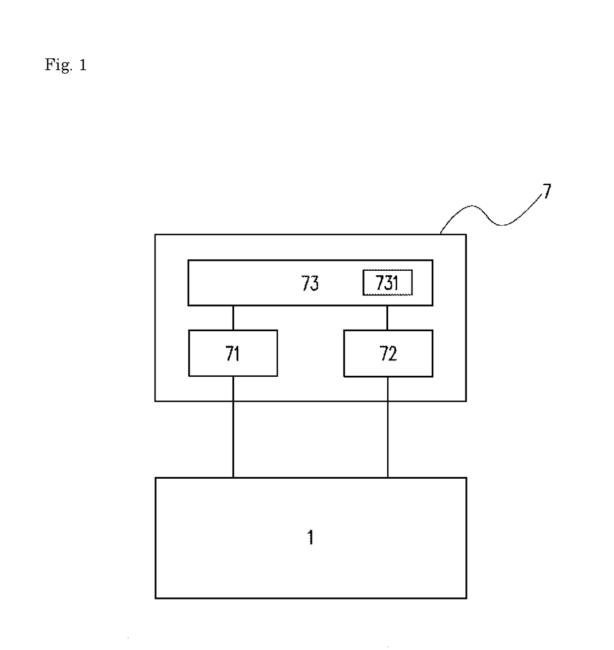
[0138]Further, the deterioration detection system 7 for the power storage element 1 according to the above embodiment may be a system that is used alone, and may be incorporated into a different system employing the power storage element 1, such as a charging system and a discharging system, for example. Further, the deterioration detection system 7 for the power storage element 1 may be incorporated into a device or the like that employs one or more power storage elements 1 as a power source.
[0139]Further, the deterioration detection system for the power storage element according to the above example is configured such that temporary deterioration is detected every time the predetermined time period (500 hours in the above example) passes, that is, at a constant period after the measuring unit starts the charge-discharge cycle endurance test, but the present invention is not limited to this example. For example, the period for detecting temporary deterioration may be shorter as the number of charge-discharge cycles increases, or may be altered based on a state of temporary deterioration (a magnitude of the increase ratio r).
[0140]The deterioration detection system 7 and the deterioration detection method for the power storage element 1 according to the above embodiment are configured such that deterioration of the power storage element 1 is detected by measuring the direct current resistance value two times before and after a use of the power storage element 1 (the use includes at least one of charging and discharging, such as the charge-discharge cycle endurance test), but the present invention is not limited to this example. The deterioration detection system 7 and the deterioration detection method for the power storage element 1 may be configured to measure the direct current resistance values three times or more. In this case, the detecting unit 73 records (stores) the first short-term resistance value and the first long-term resistance value that have been obtained in a first measurement performed to the power storage element 1 before the use in the recording unit 731 during detection of deterioration, for example. Then, the detecting unit 73 takes a short-term resistance value and a long-term resistance value obtained in n-th measurement and after (n: natural number that is 2 or more) as the second short-term resistance value and the second long-term resistance value, and obtains the first increase rate and the second increase rate based on the first short-term resistance value and the first long-term resistance value recorded (stored) in the recording unit 731, and the second short-term resistance value and the second long-term resistance value obtained in the n-th measurement.
[0141]The refresh charge according to the above embodiment is performed by continuing charging even when the SOC of the power storage element 1 reaches 100% by charging, but the present invention is not limited to this example. For example, the refresh charge may be stopped once when the SOC of the power storage element 1 reaches 100%, and then restart charging after a predetermined time period (e.g., a few seconds to several ten seconds) passes.
[0142]In the deterioration detection system 7 and the deterioration detection method for the power storage element 1 of the above embodiment, the use of the power storage element 1 between the measurement of the first short-term resistance value and the first long-term resistance value and the measurement of the second short-term resistance value and the second long-term resistance value is not particularly limited. For example, the use may be used for a power source for a tool or a machine and such that the value of the SOC changes every time when charge or discharge is started, or such that the value of the SOC when charge or discharge is started is constant as in the charge-discharge cycle endurance test.
[0143]In the deterioration detection system 7 and the deterioration detection method for the power storage element 1 according to the above embodiment, the measurement of the short-term resistance value and the long-term resistance value is performed in the high SOC state, but the present invention is not limited to this example. For example, the measurement of the short-term resistance value and the long-term resistance value may be performed in a low SOC state (the SOC is higher than 0% and lower than 50%). Even if the first and the second increase rate are obtained (calculated) using the direct current resistance values measure in the low SOC state, it is possible to detect temporary deterioration of the power storage element 1 based on a slight change in the first and the second increase rate.
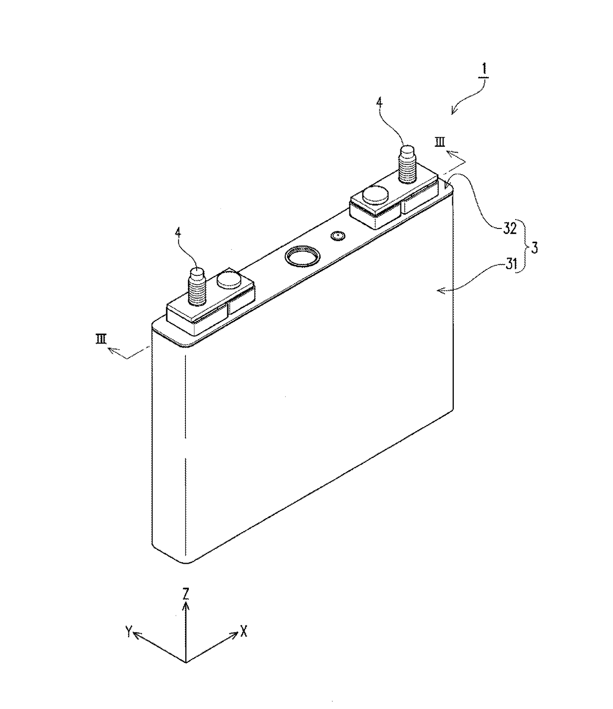
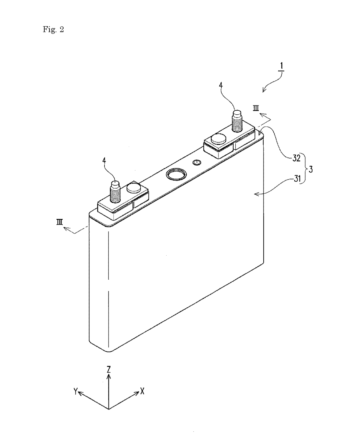
[0144]FIG. 10 is a block diagram illustrating a battery module (power storage device) 20 according to another embodiment. The battery module 20 may include a plurality of serially connected non-aqueous electrolyte power storage elements 30, a battery manager 50 that manages the power storage elements 30, and a current sensor 40 that detects a current flowing through the power storage elements 30. The battery module 20 is charged by a charger 10, and supplies direct current power to an inverter (load 10) that drives a motor for driving a vehicle or the like. The power storage elements 30 may be lithium ion batteries including, for example, a graphite-based negative active material and an iron phosphate based positive active material such as LiFePO4.
[0145]The battery manager 50 includes a control unit 60, a voltage measurement unit 70, and a current measurement unit 80. The control unit 60 includes a central processing unit (CPU) 61, and a memory 63. The memory 63 records various programs for controlling an operation of the battery manager 50. The battery manager 50 may be configured by mounting various devices on one or more substrates.
[0146]The voltage measurement unit 70 is connected to both terminals of the power storage elements 30 via voltage detection lines, and measures a voltage V (V) of each of the power storage elements 30 at predetermined intervals. The current measurement unit 80 measures a current flowing through the power storage elements 30 via the current sensor 40.
[0147]The battery module 20 may be a battery module for driving electric vehicles such as an electric vehicle (EV), a hybrid electric vehicle (HEV), and a plug-in hybrid electric vehicle (PHEV). It is possible to perform charging using an alternator in a short time period and at a high current (e.g., up to 10 CA, 10-30 seconds).
[0148]When the battery module 20 is used to drive a PHEV, the battery module 20 may perform the deterioration detection method shown in FIG. 5 once a month. The battery module 20 may perform the deterioration detection method shown in FIG. 5 in a routine vehicle inspection that takes place once two years.
[0149]Alternatively, the battery module 20 may perform the deterioration detection method shown in FIG. 5 daily or once in two to three days, for example, during plug-in charge using an electric outlet for household use (0.2-1 CA, a few hours).
[0150]The battery module 20 may be configured as a battery pack containing the power storage elements 30, the current sensor 40, and the battery manager 50 in a single container. The battery pack may be a starter battery for starting engines (12 V power source) mounted on moving vehicles such as vehicles, trains, ships, and airplanes.
[0151]The battery module 20 may be a 48 V power source for assisting vehicle driving. In this case, the battery module 20 may also perform the deterioration detection method shown in FIG. 5 at the same timing as in the use for driving a PHEV.
[0152]In the example shown in FIG. 10, the container containing the power storage elements 30 also includes the control unit 60, but the present invention is not limited to such an example. The control unit may be disposed at a position distant from the power storage elements. For example, a control unit mounted on a vehicle may serve as the control unit for the deterioration detector.

PUM

no PUM

Description & Claims & Application Information

We can also present the details of the Description, Claims and Application information to help users get a comprehensive understanding of the technical details of the patent, such as background art, summary of invention, brief description of drawings, description of embodiments, and other original content. On the other hand, users can also determine the specific scope of protection of the technology through the list of claims; as well as understand the changes in the life cycle of the technology with the presentation of the patent timeline. Login to view more.
Why Eureka
Try Eureka