Electric shaver

a technology of electric shaver and shaver blade, which is applied in the direction of metal working apparatus, etc., can solve the problems of affecting the comfort of shaver handling, affecting the balance of the entire shaver, and affecting the smooth operation of the shaver

Active Publication Date: 2018-03-29
BRAUN GMBH
View PDF3 Cites 27 Cited by
  • Summary
  • Abstract
  • Description
  • Claims
  • Application Information

AI Technical Summary

Benefits of technology

The goal of this improvement is to make an electric shaver that can adjust its own position without being affected by other parts of the machine or any collisions between them. This will improve the performance of the shaver and reduce friction during use.

Problems solved by technology

This patent describes various ways to connect the cutter elements (also called blades) of an electric shaver to the main body of the machine. However, these methods often result in unbalanced devices, making them hard to hold and control during shaving. There is a technical problem in finding a way to connect the blade system to the main body without compromising balance, while still being able to make small changes in position to match the contour of the skimming surface.

Method used


Image

  • Electric shaver
  • Electric shaver
  • Electric shaver

Examples


Embodiment Construction

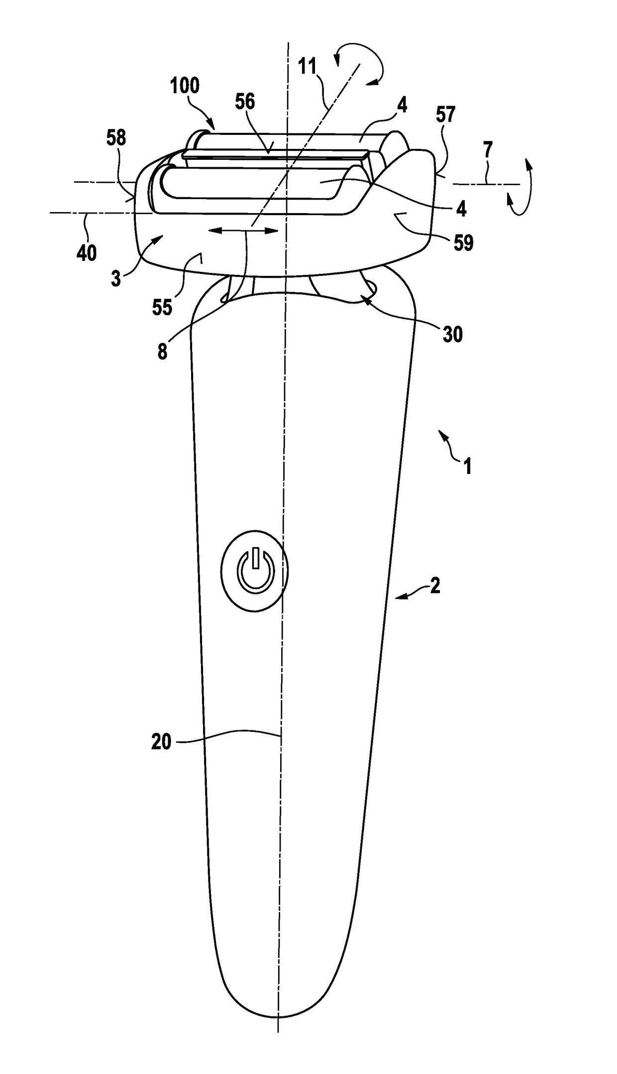
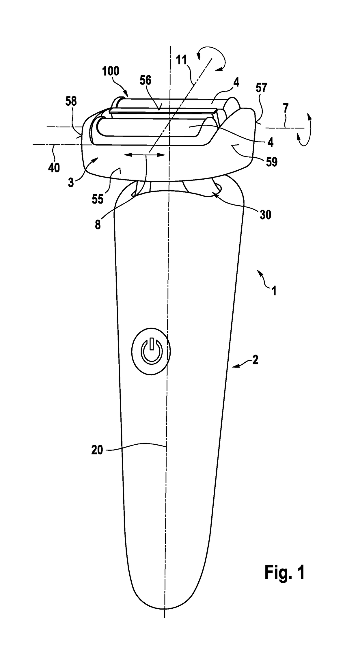
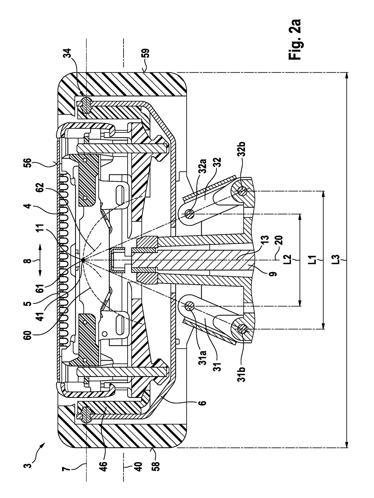
[0036]In order to achieve a responsive self-adjustment of the angular position of the cutter element to the skin and to avoid collisions between the drive train for driving the cutter element and the support structure, the four-joint linkage may include a pair of link arms arranged in an upright, standing configuration where the head joints of the link arms connected to the shaver head part are further away from the handle than the handle joints of the link arms connected to the handle or a base part connected to such handle. Such standing link arm configuration does not only give the drive train more space to extend in the region of the support structure, but also improves the shaver head kinematics to allow angular adjustment of the shaver head under less contact pressure from the skin to be shaved as the standing link arms are more willing to leave its position than hanging pendulum arms. In addition, such standing link arm configuration allows for an improved arrangement of the ...


PUM


Abstract

Electric shaver provided with a handle and a shaver head including at least one drivable cutter element, wherein said shaver head is connected to said handle by means of a support structure providing for a swivel and/or tilting axis about which said shaver head may swivel or tilt relative to said handle, wherein said support structure includes a pair of link arms forming a four-joint linkage with each link arm having a head joint connected to a shaver head part and a handle joint connected to the handle or a base part connected thereto.

Description


Claims


Application Information

Patent Timeline
Owner BRAUN GMBH
Why Eureka
Try Eureka