
Illumination system for an automotive vehicle

a technology for automobiles and a system of abrasives, applied in the field of abrasives, can solve the problems of inability to solve the resolution problem of this type of technology, inherent limitations of existing technology, and poor resolution and freedom limitation of their technology, and achieve the effect of simplifying the graphic representation of drawings

Active Publication Date: 2018-03-29
VALEO VISION SA
View PDF3 Cites 20 Cited by
  • Summary
  • Abstract
  • Description
  • Claims
  • Application Information

AI Technical Summary

Benefits of technology

The invention allows for better illumination of the road for a vehicle driver, making it easier to see and read the information projected onto the road. It also allows for more precise and higher quality contrast management and higher resolution. The vehicle driver can have a more comfortable experience and the projected information can be managed more intelligently based on environmental parameters.

Problems solved by technology

Existing high beams also have similar drawbacks, namely very poor resolution and degrees of freedom limited by their technology.
Although improvements have been proposed for high beams, for example the use of two identical devices for strip illumination, this does not solve the problem of the resolution that this type of technology can achieve.
Here again, however, this type of system has many drawbacks, since it is desirable to adapt the projection of light beams to specific and variable external conditions.
In fact, there is an inherent limitation on the existing technology, due to the choice between illumination power and illumination resolution.
Existing high-resolution systems cannot provide the illumination characteristics of low-resolution systems, and it is difficult for low-resolution systems to achieve the visual quality of DMD systems.

Method used


Image

  • Illumination system for an automotive vehicle
  • Illumination system for an automotive vehicle
  • Illumination system for an automotive vehicle

Examples


Embodiment Construction

[0040]In the following description, similar reference numerals will be used to describe similar concepts, based on different embodiments of the invention.

[0041]Unless specified otherwise, technical characteristics described in detail for a given embodiment may be combined with the technical characteristics described in the context of other embodiments described by way of example and in a non-limiting way.

[0042]As a general rule, the present invention may use light sources of the light-emitting diode type, also commonly called LEDs. Notably, these LEDs may be equipped with at least one chip capable of emitting light whose intensity is advantageously adjustable according to the illumination and / or signaling function to be provided. There may be a plurality of sources, as described more fully below. Furthermore, the term “light source” is here taken to mean a set of at least one elementary source such as an LED, capable of producing a flux causing an output light beam, executing at lea...


PUM


Abstract

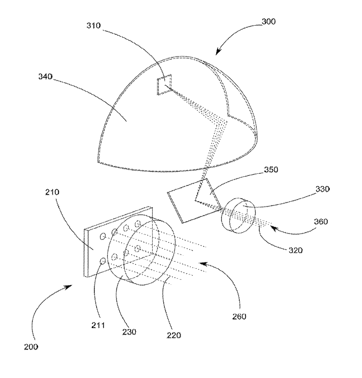
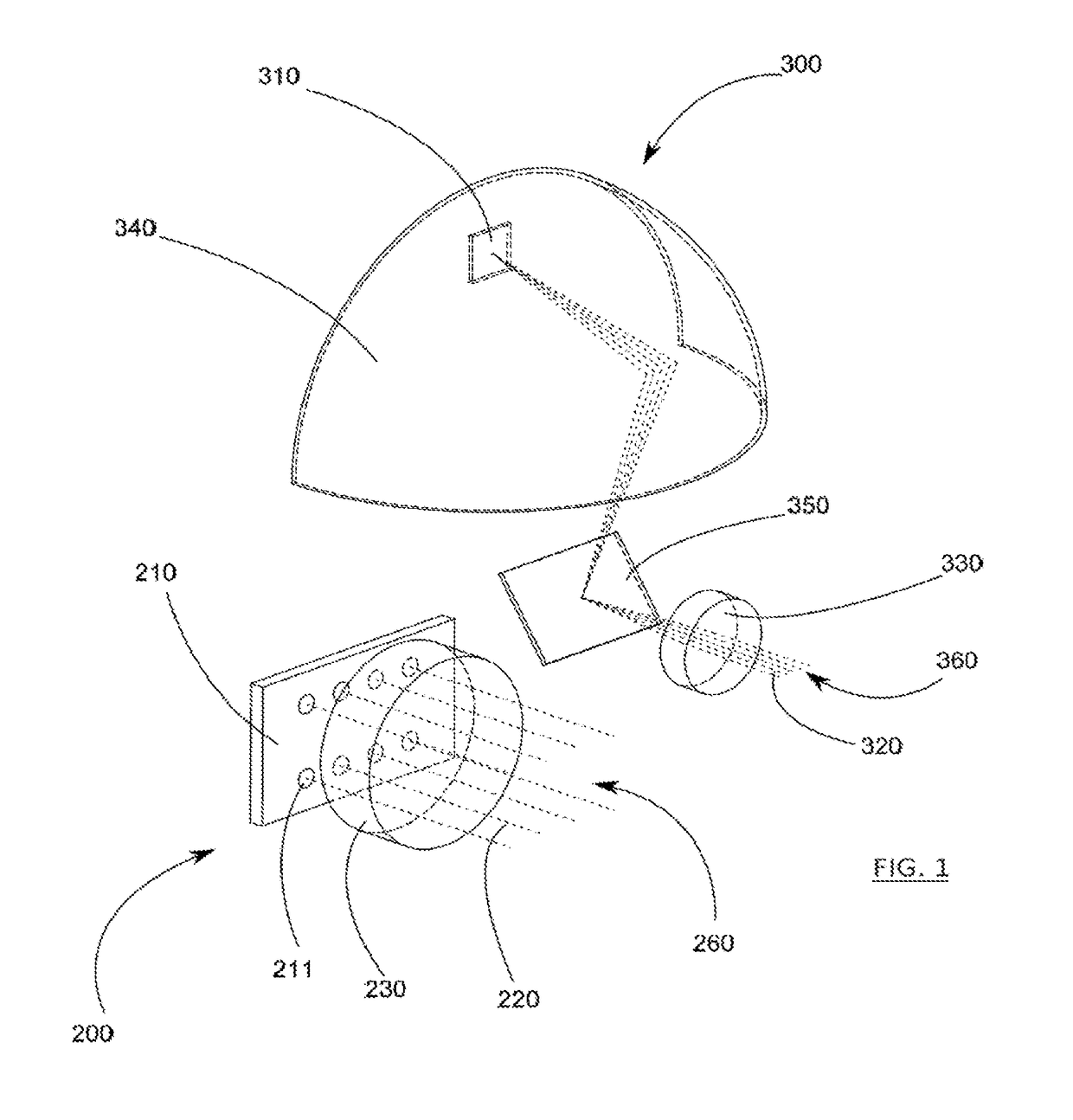
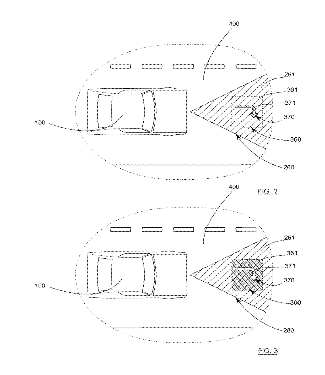
The present invention relates to an illumination system for a vehicle, including at least a first projection device for projecting at least one pixelated light source defining at least a first projection envelope and at least a second projection device for projecting at least one pixelated light beam defining at least a second projection envelope and configured to project at least one pictogram, wherein at least a first projection envelope and the at least a second projection envelope have at least one area of overlap.

Description

TECHNICAL FIELD OF THE INVENTION[0001]The present invention relates, notably, to an illumination system. A preferred application concerns the automotive industry, for vehicle equipment, in particular for the provision of devices capable of emitting light beams, also called illumination functions, which generally conform to regulations. The emission of beams ahead of the vehicle is of particular relevance.PRIOR ART[0002]Up to the present time, known illumination and signaling devices have been designed in order to emit, for example, a low beam, a high beam, an illumination beam for foggy weather, and a signaling beam.[0003]The low beam must provide both good quality illumination and an absence, or reduction, of the annoyance to surrounding vehicles caused by the luminous flux produced. At present, low beam headlights are essentially designed for this purpose, use being made, in particular, of cut-offs, which may be complex, at the top of the beam, in order to limit precisely, or prev...

Claims


Application Information

Patent Timeline
IPC IPC(8): B60Q1/50B60Q1/26G03B21/00B60Q1/00
CPCB60Q1/50B60Q1/2607G03B21/008B60Q1/0076B60Q2400/50B60Q1/34B60Q2300/42B60Q2300/41B60Q2300/314B60Q2300/312B60Q2300/45B60Q2300/114B60Q1/04B60Q1/14B60Q1/143B60Q1/1438B60Q1/18F21S41/153F21S41/36F21S41/663F21S41/675F21S41/365B60Q1/545
Inventor MOREL, XAVIERLUO, WEICHENG
Owner VALEO VISION SA
Learn More