Eureka AIR delivers breakthrough ideas for toughest innovation challenges, trusted by R&D personnel around the world.

Biased angle screws

a technology of biasing angle and screw, which is applied in the direction of internal osteosythesis, fasteners, and osteosythesis devices, can solve the problems of strong constructions with low profiles, and achieve the effects of low profile, increased angulation, and maintaining structural stability

Inactive Publication Date: 2018-04-26
STRYKER EURO HLDG I LLC
View PDF2 Cites 4 Cited by
  • Summary
  • Abstract
  • Description
  • Claims
  • Application Information

AI Technical Summary

Benefits of technology

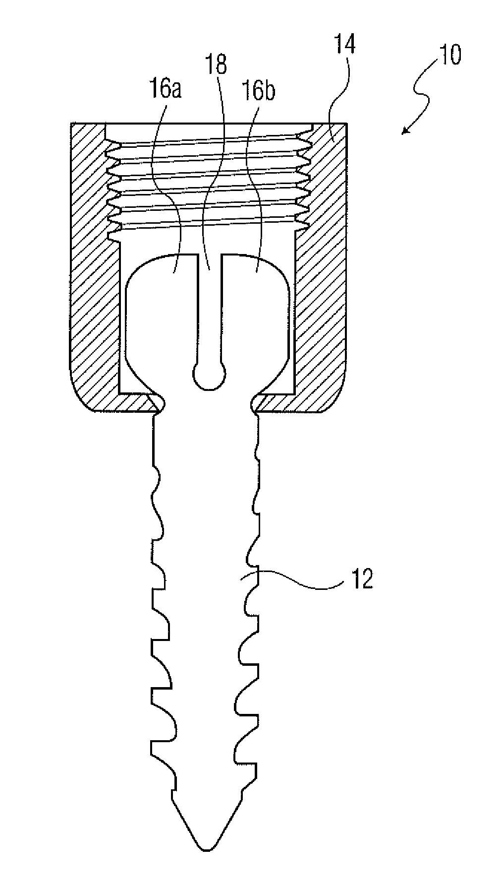
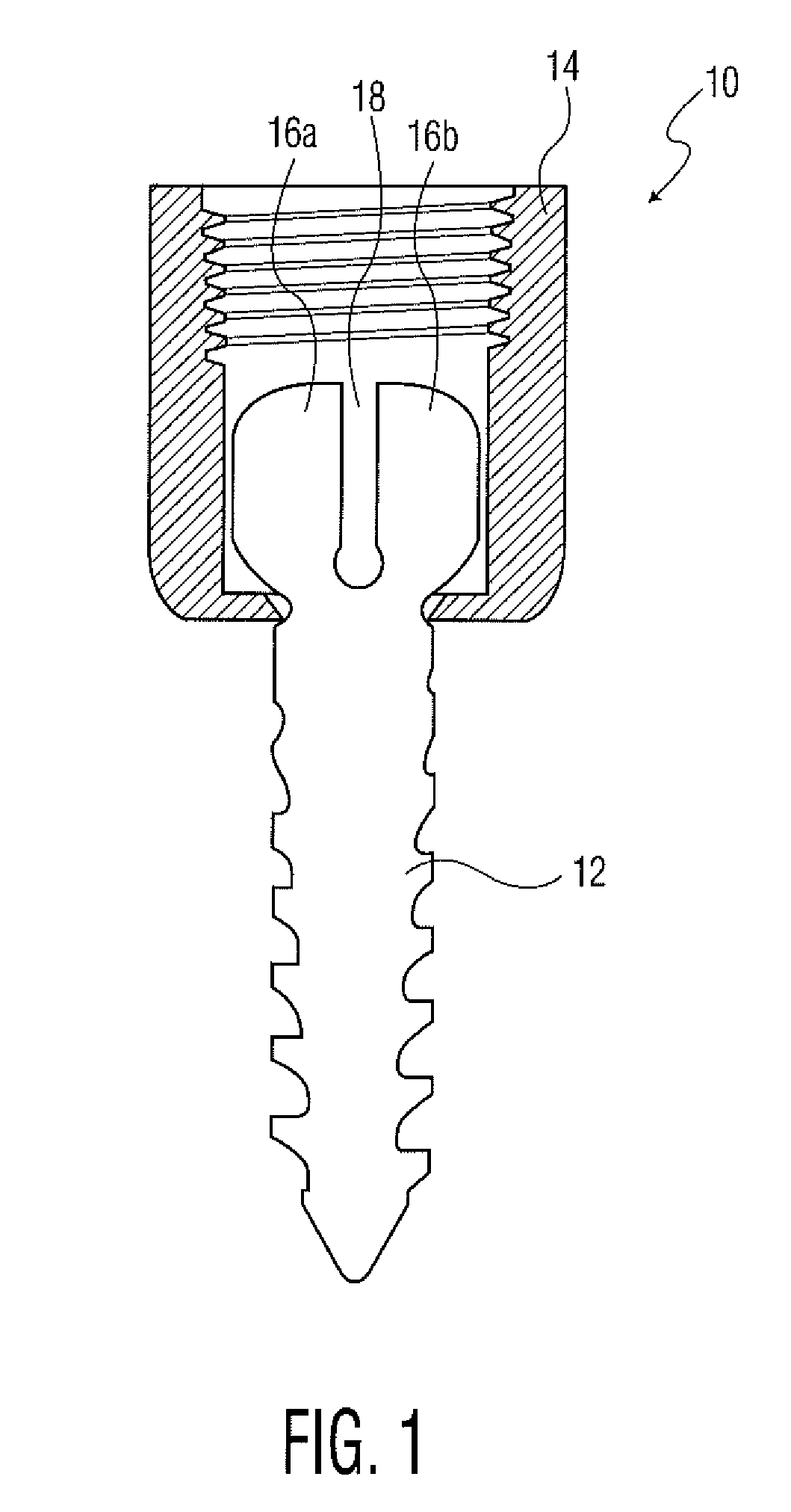
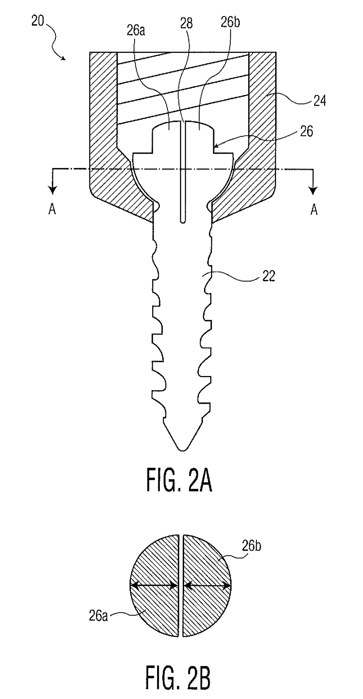
[0006]Various embodiment biased angle pedicle screws are disclosed in the present application. Each addresses the need for increased angulation, while at the same time maintaining structural stability. This results in strong constructs with low profiles.

Problems solved by technology

This results in strong constructs with low profiles.

Method used


Image

  • Biased angle screws
  • Biased angle screws
  • Biased angle screws

Examples


Embodiment Construction

[0032]When referring to the specific directions in the following discussion of certain surgical instruments, it should be understood that such directions are described with regard to the surgical instruments orientation and position during exemplary application of the human body. Thus, as used herein, the term “proximal” means close to the heart, and the term “distal” means more distant from the heart. The term “anterior” means toward the front of the body or the face, and the term “posterior” means toward the back of the body. The term “medial” means toward the midline of the body, and the term “lateral” means away from the midline of the body. Also, as used herein, the terms “about,”“generally” and “substantially” are intended to mean that slight deviations from absolute are included within the scope of the terms so modified.

[0033]Following below is a discussion of several different embodiment biased angle pedicle screws in accordance with the present invention. In each case, the ...


PUM


Abstract

Several different embodiment pedicle screws are disclosed. The designs allow for increased angulation between the screw portions and coupling elements, which may be particuarly useful for cervical vertebrae fusion procedures. Methods of utilizing the pedicle screws are disclosed herein.

Description

CROSS-REFERENCE TO RELATED APPLICATION[0001]The present application is a continuation of U.S. patent application Ser. No. 14 / 869,090, filed on Sep. 29, 2015, the disclosure of which is incorporated herein by reference.BACKGROUND OF THE INVENTION[0002]Spinal fusion procedures involving pedicle screw fixation are common spinal procedures for addressing back and neck pain in patients. In a typical procedure, a surgeon will install pedicle screws into the pedicles of adjacent vertebrae (along one or multiple levels of the spine) and thereafter place a spinal rod in coupling elements of pedicle screws. Once in the desired position, the pedicle screws may be locked with a set screw or the like thereby fixing the adjacent vertebrae in position. Whether conducted in conjunction with interbody fusion or across single or multiple levels of the spine, the use of pedicle screws connected by fixation rods is an important treatment method employed by spinal surgeons.[0003]The different levels of ...

Claims


Application Information

Patent Timeline
Patent Type & Authority Applications(United States)
IPC IPC(8): A61B17/70A61B17/86
CPCA61B17/8605A61B17/7032A61B17/7038A61B17/7037
Inventor BUSH, JR., CHARLES L.
Owner STRYKER EURO HLDG I LLC
Why Eureka
Eureka Blog
Learn More