

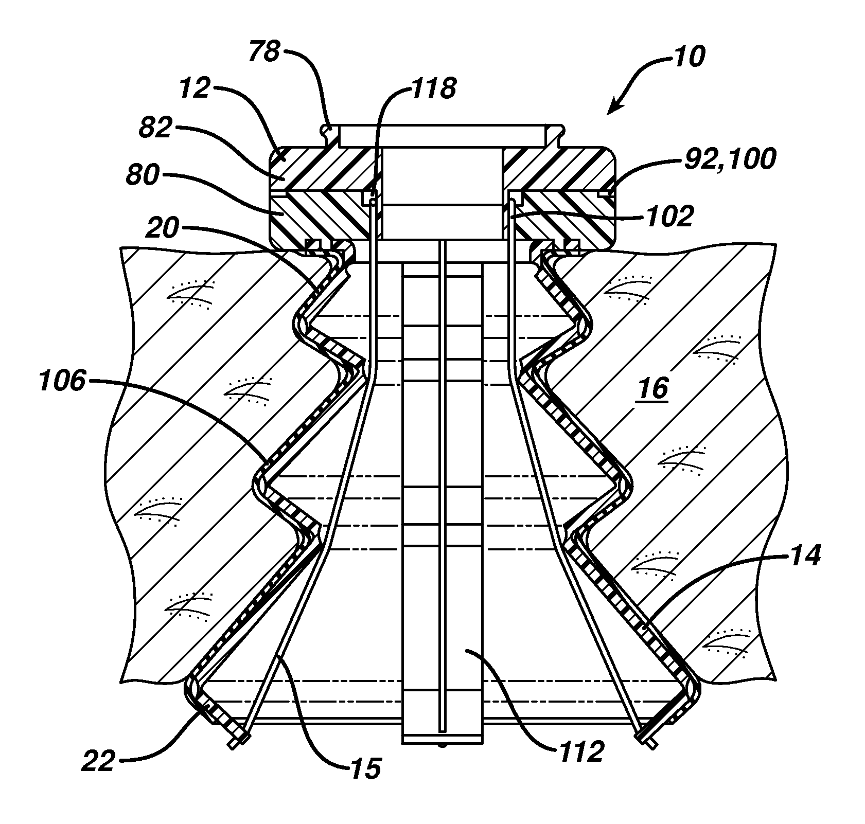
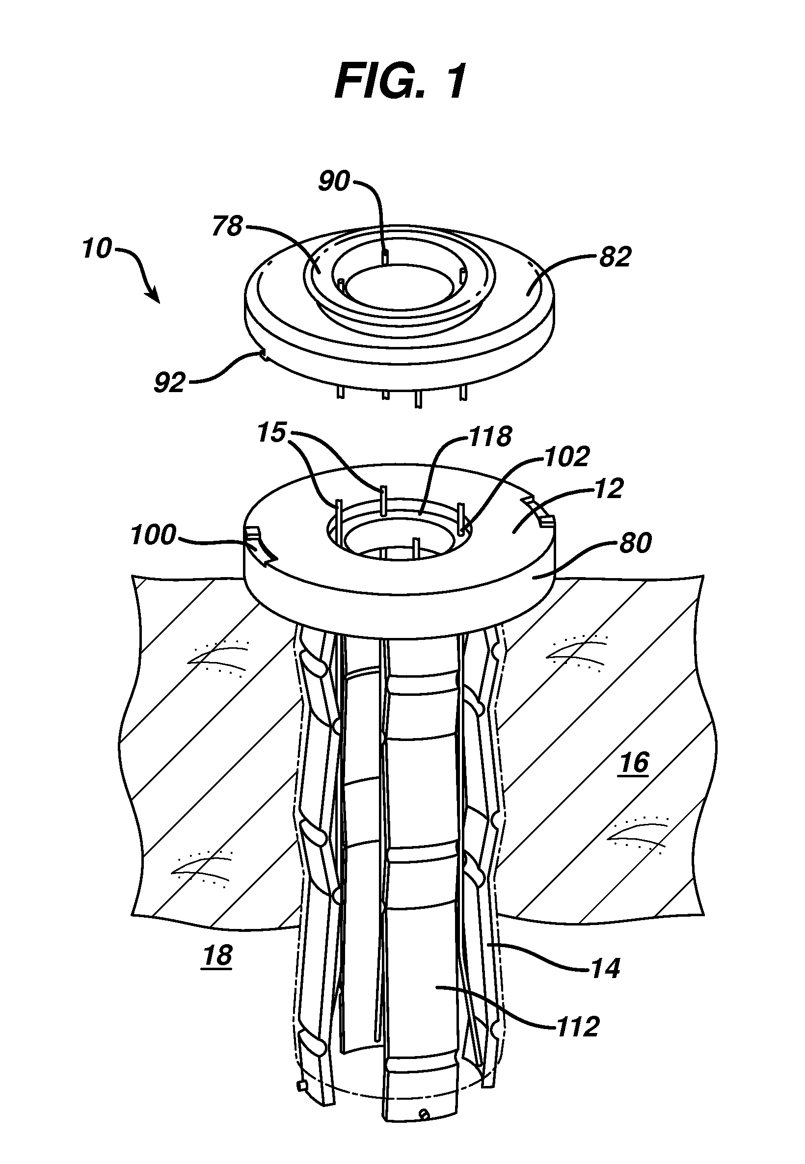
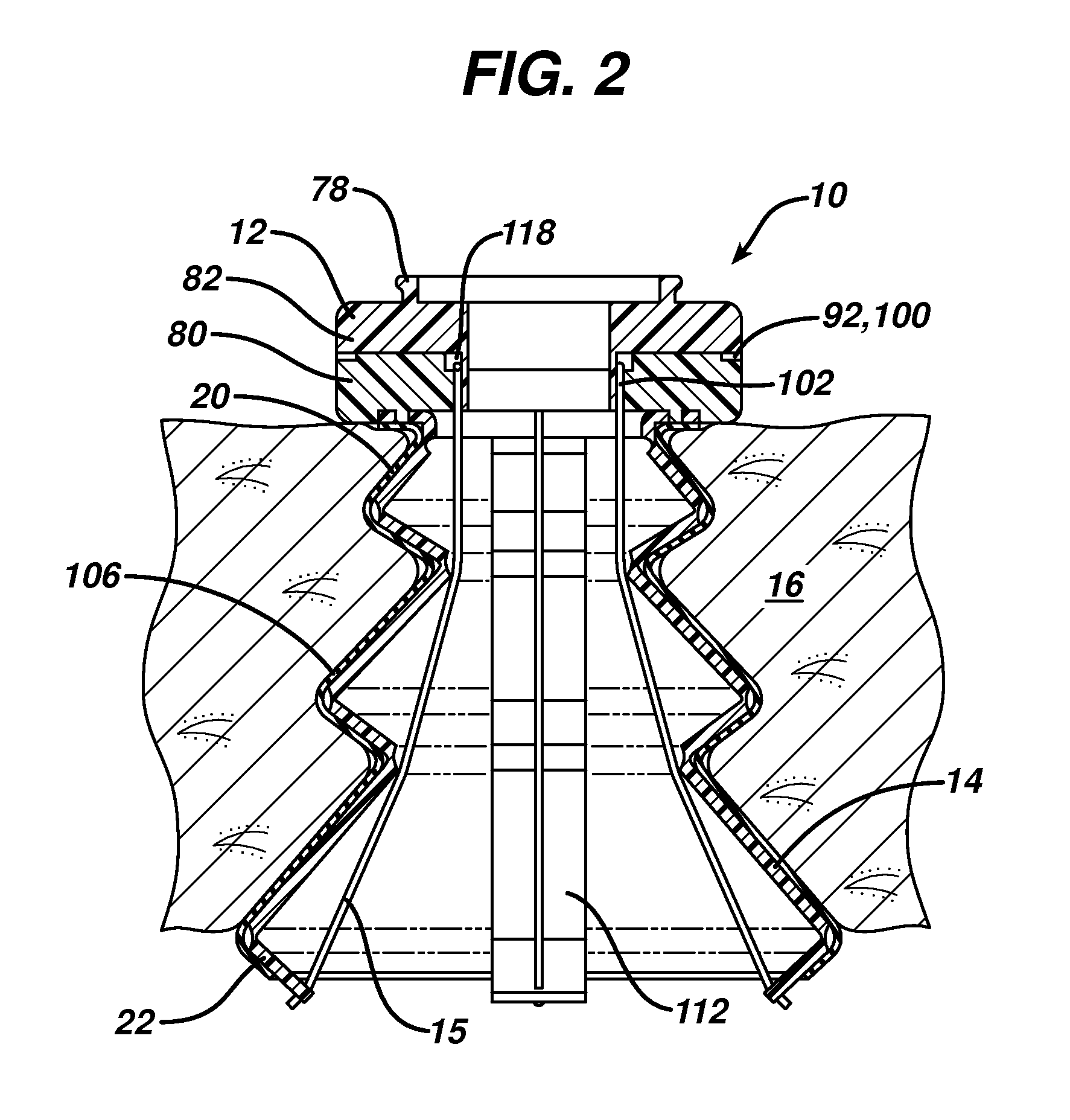
Inverted conical expandable retractor
a retractor and conical technology, applied in the field of body cavity access devices, can solve the problems of limiting the degree to which devices passed through the cannula can be angulated with respect to the operative field, undesirably prolonging and complicating surgery, and suffering from poor retention and sealing capabilities, so as to improve the retention of the access device, improve the angulation of the instruments passed, and increase the integrity of the seal formed
- Summary
- Abstract
- Description
- Claims
- Application Information
AI Technical Summary
Benefits of technology
Problems solved by technology
Method used
Image

Examples
Embodiment Construction
[0055]Certain exemplary embodiments will now be described to provide an overall understanding of the principles of the structure, function, manufacture, and use of the devices and methods disclosed herein. One or more examples of these embodiments are illustrated in the accompanying drawings. Those skilled in the art will understand that the devices and methods specifically described herein and illustrated in the accompanying drawings are non-limiting exemplary embodiments and that the scope of the present invention is defined solely by the claims. The features illustrated or described in connection with one exemplary embodiment may be combined with the features of other embodiments. Such modifications and variations are intended to be included within the scope of the present invention.
[0056]A person skilled in the art will appreciate that, while methods and devices are described herein in connection with minimally invasive laparoscopic procedures in the abdominal cavity, the method...
PUM
 Abstract
Description
Claims
Application Information