Pressure cooking appliance

a technology of pressure cooker and cooking utensils, which is applied in the field of counter top cookers, can solve the problems of inability to achieve the effect of cooking in a pressure cooker, the limitation of the related art, and the inability to maintain a positive pressure in an elongated or oval cooking utensils such as those of the prior ar

Inactive Publication Date: 2018-06-07
GLUCKSMAN DOV Z
View PDF7 Cites 63 Cited by
  • Summary
  • Abstract
  • Description
  • Claims
  • Application Information

AI Technical Summary

Benefits of technology

[0010]The invention may be embodied in or practiced using a countertop kitchen appliance having a cooking chamber with a side wall and a first rim defining a first opening to a cavity, an electric heating element disposed proximate the cavity to heat the cavity, a lid sized and shaped to cover the first rim when placed there-on, one or more hinges pivotably connecting the lid to the sidewall and enabling the lid to pivot between an opened position for accessing the cavity and a closed position for covering the cavity, one or more latches for voluntarily securing the lid to the side wall, each having an unlatched position for allowing the lid to pivot relative to the sidewall, and a latched position for engaging the lid to the sidewall in the closed position, a pressure seal disposed between the lid and the first rim and compressed there-between when the lid is in the closed position and the latch is in the latched position, and a pressure-regulating valve communicating between the cavity and an exterior environment and adapted to prevent pressure within the cavity from exceeding a first predetermined pressure level relative to the exterior environment.
[0011]The appliance may further have a pressure responsive lock for involuntarily securing the lid in the closed position when the pressure within the cavity exceeds a second predetermined pressure level. The appliance may include a pan sized and shaped to fit within the cavity and having a generally hollow interior and a second rim defining a second opening for accessing the generally hollow interior. The one or more latches may be at least two latches, and the one or more hinges and at least two latches may be approximately equally spaced about the first rim. The appliance may have a control for maintaining the heating of the cavity at a predetermined temperature level. The pressure-regulating valve may be adjustable to vary the predetermined pressure level. The appliance may be longer from a left side to a right side than from a front side to a rear side. The at least two latches may be two latches disposed adjacent the left and right sides and the one or more hinges may be disposed on the front side.
[0012]The inven...

Problems solved by technology

These higher temperatures are required to roast food such as chicken, turkey, pork or beef where the outer layer must be crisp and browned, something that cannot be achieved by cooking in a pressure cooker.
It was determined from experiments that maintaining a positiv...

Method used


Image

  • Pressure cooking appliance
  • Pressure cooking appliance
  • Pressure cooking appliance

Examples


Embodiment Construction

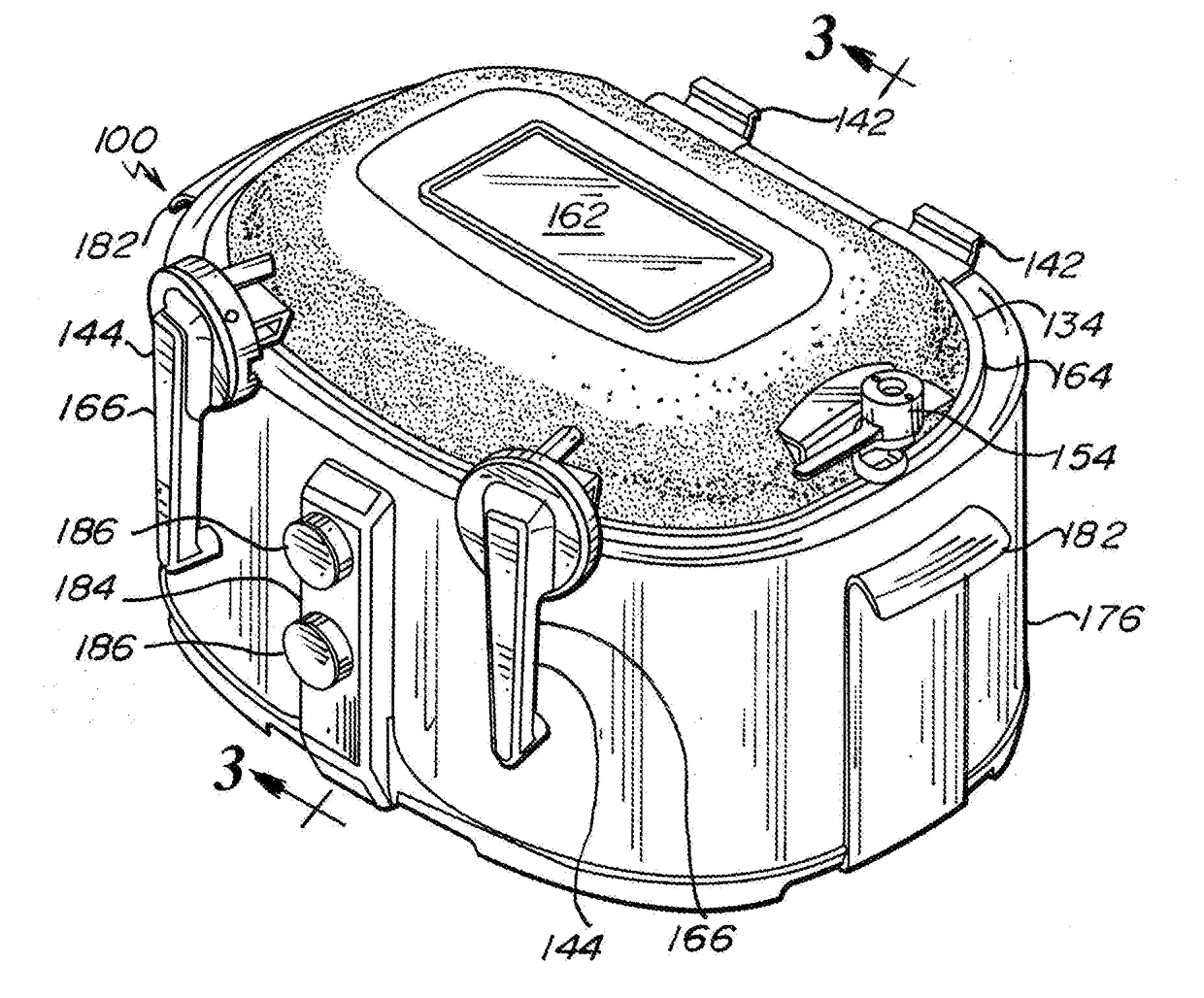
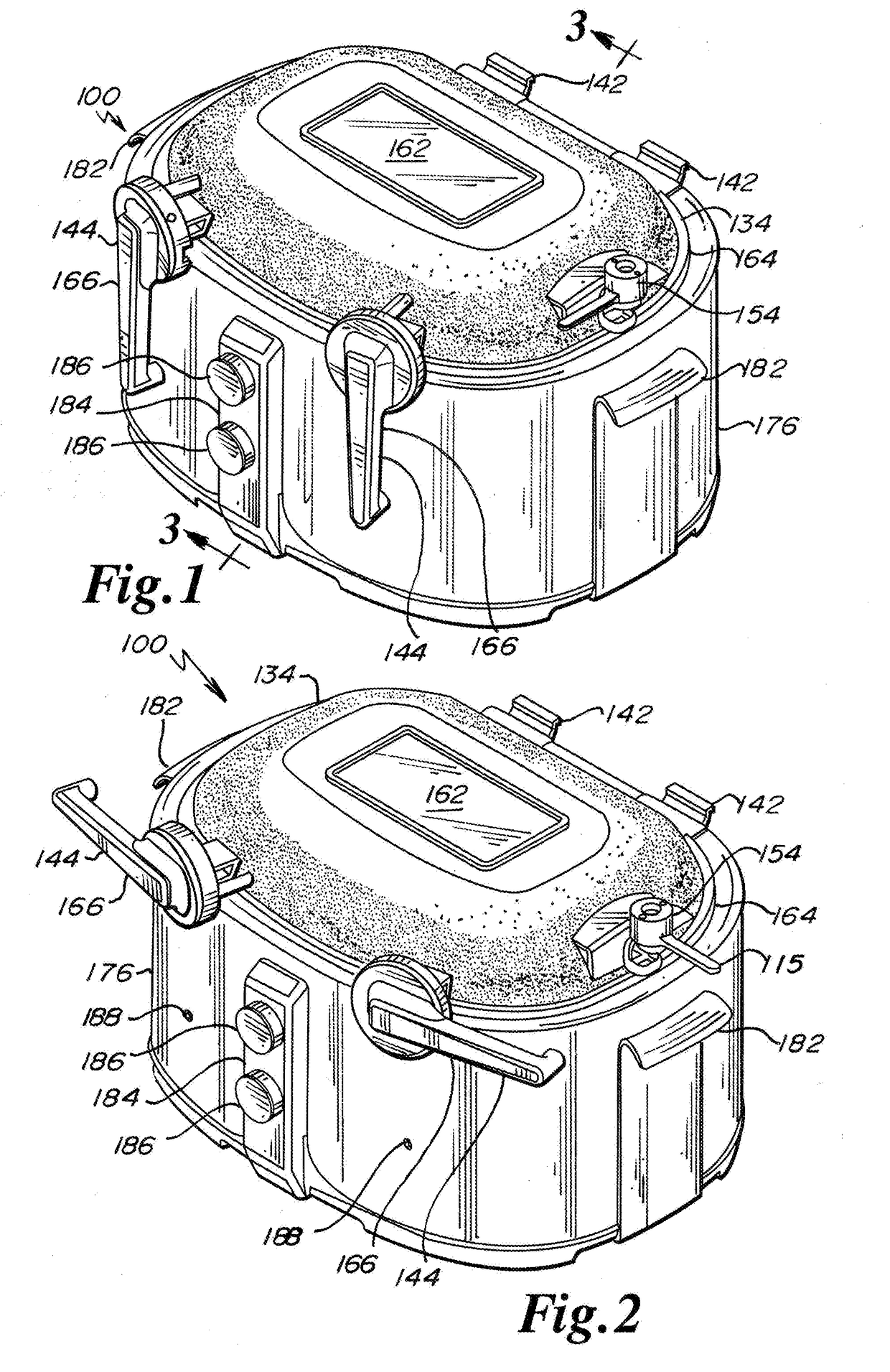
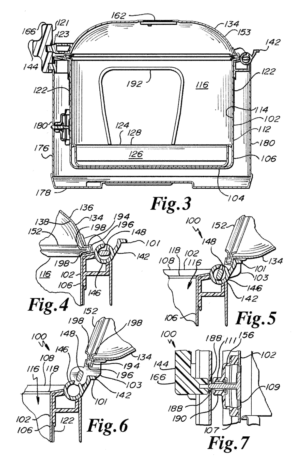
[0037]FIGS. 1 through 11 show a first exemplary embodiment of a pressure roasting appliance in accordance with or useful in practicing the invention.

[0038]The appliance 100 has a cooking chamber 102 with a base 104 with a side wall 106 extending upwardly there-from to an upper rim 108. The side wall has an exterior surface 112 and an opposing interior surface 114. At least portions of the interior surface of the side wall and base define a cavity 116 within the cooking chamber. The cooking chamber's rim 108 is disposed at a first, free upper edge of the side wall to define an opening 118 to the cavity. A heating element 122 is disposed within the cooking chamber proximate the cavity to heat the cavity. A pan 124 has a generally hollow interior 126 and a rim 128 defining an opening for accessing the interior 126. The interior of the pan can retain food contents therein. The pan is sized and shaped to fit within the cavity of the cooking chamber. A lid 134 is sized and shaped to at le...


PUM


Abstract

An oval shaped countertop kitchen appliance having a cooking chamber that defines a cavity. The cooking chamber has a rim defining an opening to the cavity. An electric heating element is disposed proximate the cavity to heat the cavity. A pan retaining foodstuff therein has a generally hollow interior and a rim defining an opening for accessing the interior thereof. The pan is sized and shaped to fit within the cavity of the cooking chamber. A lid is sized and shaped to at least partially cover the cooking chamber rim when placed on the cooking chamber rim. At least one hinge and one latch are mounted to one of the exterior surface of the side wall of the cooking chamber and the lid. A pressure seal is present in the interface of the lid and the cooking chamber rim. Said pressure seal is compressed when latching mechanism is in its latched position. Pressure regulating valve communicates between the cooking chamber cavity and the outside, to limit the pressure built up within the cooking chamber as foodstuff is heated by said electric heater and emits steam during the cooking process. Said cooking pressure is set at a predetermined level. Temperature in the cooking chamber is controllable by the user as is the duration of the cooking cycle.

Description

RELATED APPLICATION[0001]This application claims the benefit of U.S. Provisional Applications No. 62 / 428,623 filed on 1 Dec. 2016, No. 62 / 446,579 filed on 16 Jan. 2017, and No. 62 / 547,909 filed on 21 Aug. 2017, the teachings of which are all claimed herein by reference in their entireties.FIELD OF THE INVENTION[0002]This invention relates generally to kitchen appliances, and more particularly to a countertop cooker where food can be cooked at high temperatures under a slightly elevated pressure.BACKGROUND[0003]Kitchen appliances, such as slow cookers and counter top roasters, are well known. Conventional slow cookers and roasters are generally elongated or oval, as they are used, for example for roasting a whole turkey or a large chicken, or a rack of ribs. On the other hand, pressure cookers, where food is cooked under relatively high-pressure conditions ranging from 10 to 20 psi (0.7 to 1.5 bar) have a round lid, primarily since it is much easier to seal a round perimeter than an ...

Claims


Application Information

Patent Timeline
IPC IPC(8): A47J27/08
CPCA47J27/0815A47J27/0811A47J27/004
Inventor GLUCKSMAN, DOV Z.ROJEE, ANDREW JOSEPHMILLER, MICHAEL DAVID
Owner GLUCKSMAN DOV Z
Why Eureka
Try Eureka