Clip for mounting external device to electronic device

a technology for mounting clips and external devices, applied in the direction of printing, instruments, transportation and packaging, etc., can solve the problems of difficult to ensure the device is mounted, and achieve the effect of enhancing the capability

Active Publication Date: 2018-06-07
REDWOODVENTURES
View PDF24 Cites 5 Cited by
  • Summary
  • Abstract
  • Description
  • Claims
  • Application Information

AI Technical Summary

Benefits of technology

The patent text describes a problem where it can be hard to make sure that a device is aligned properly when it is attached to a smartphone. This can make it difficult for the device to work with the smartphone in the way it is intended.

Problems solved by technology

The patent text discusses the use of mounting systems for adding extra features to smartphones, such as camera lens systems for zooming in. However, it can be difficult to make sure that the extra device is aligned correctly with the feature it is intended to work with. The technical problem is how to ensure that the extra device is in suitable alignment with the feature of the smartphone it is intended to cooperate with.

Method used


Image

  • Clip for mounting external device to electronic device
  • Clip for mounting external device to electronic device
  • Clip for mounting external device to electronic device

Examples


Embodiment Construction

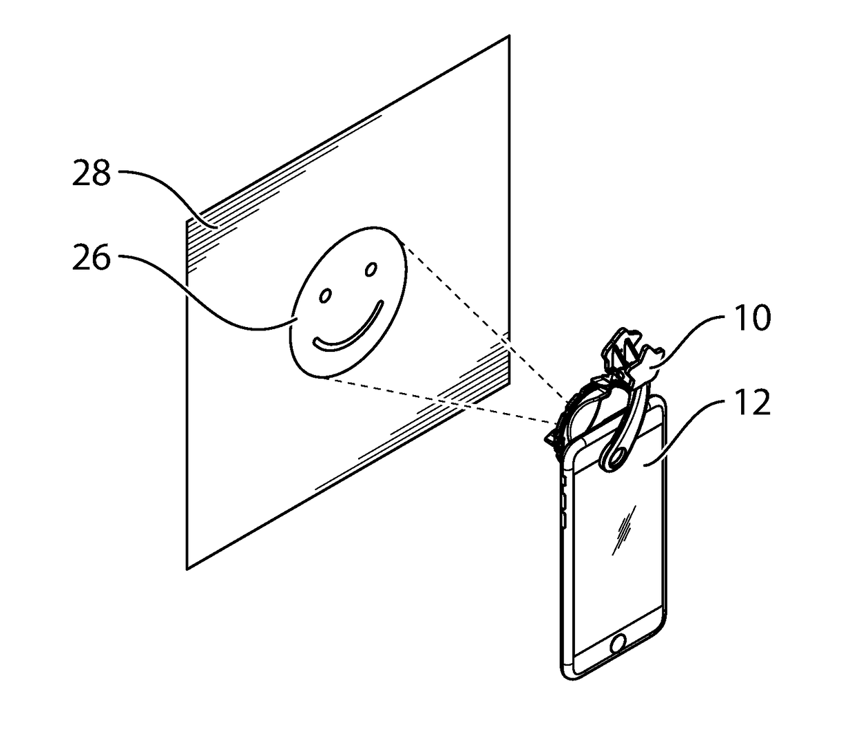
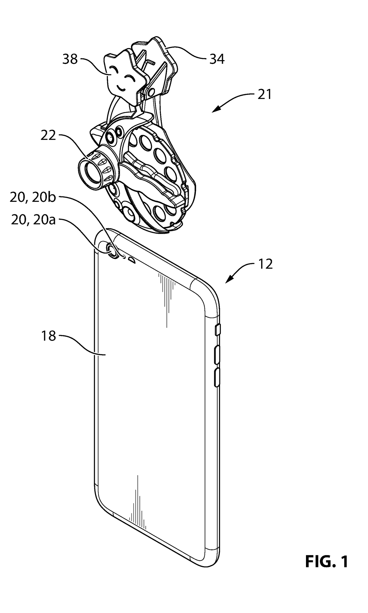
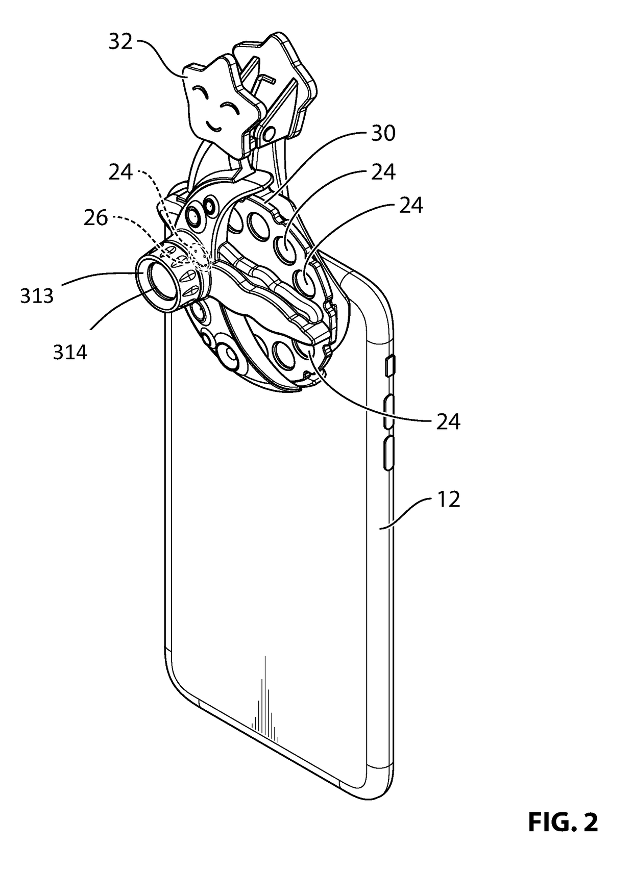
[0022]Reference is made to FIGS. 1, 2 and 3, which show a device-and-clip system for an electronic device 12 such as a smartphone or a tablet. The device-and-clip system is configured to permit a user to properly position and use an external device with the electronic device 12. The electronic device may also be referred to as a mobile device 12.

[0023]The electronic device 12 has a front face 14 (FIG. 3) with a display screen 16 thereon, and a rear face 18 (FIGS. 1 and 2) opposite to the front face 14. The rear face 18 has at least one electronic device feature 20 thereon. In the present example, the rear face 18 has a plurality of features 20, including a camera 20a, and a light-emitting element 20b, which may be, for example, an LED. In some embodiments, the light-emitting element 20b may serve as a camera flash and as a flashlight on the electronic device 20. For greater certainty, the term ‘camera flash’ is used in various places in the present disclosure, however it is merely a...


PUM


Abstract

In an aspect, a device-and-clip system is provided for an electronic device. The system includes an external device that cooperates with at least one electronic device feature on the rear face to perform a selected function. The system includes a clip including a first clip arm having an arm marker thereon and which is engageable with the front face of the electronic device and a second clip arm that is engageable with the rear face of the electronic device. The system further includes an application that is executable to instruct the electronic device to display a screen marker on the display screen in a selected position and in a selected orientation such that positioning and orienting of the first clip arm on the display screen of the smart phone with the arm marker aligned with the position and orientation of the screen marker positions the external device in alignment with the at least one electronic device feature.

Description


Claims


Application Information

Patent Timeline
Owner REDWOODVENTURES
Why Eureka
Try Eureka