Power limiting stress-strain monitor system and method for machine

a monitor system and stress-strain technology, applied in the direction of instruments, force/torque/work measurement apparatus, construction, etc., can solve the problems of significant cost, structural failure, and equipment structural components are often subject to stress-strain, and achieve the effect of reducing power control

Active Publication Date: 2018-06-21
CATERPILLAR INC
View PDF3 Cites 0 Cited by
  • Summary
  • Abstract
  • Description
  • Claims
  • Application Information

AI Technical Summary

Benefits of technology

[0005]In one aspect, a power limiting stress-strain monitor system for a machine includes at least one stress-strain sensor supported on a structural component of the machine. The power limiting stress-strain monitor system also includes an electronic controller including a processor and a memory. The processor receives a signal from the stress-strain sensor, determines a degree of stress-strain at a location of the stress-strain sensor based on the signal, identifies a machine system associated with the stress-strain, and modifies a control signal to the machine system based on the degree of stress-strain.
[0006]In another aspect, a machine having a power limiting stress-strain monitor system supported thereon is provided. The machine includes a machine frame, ground-engaging propulsion elements supported on the machine frame, and an electronic controller including a processor and a memory. The processor receives a signal from the stress-strain sensor, determines a degree of stress-strain at a location of the stress-strain sensor based on the signal, identifies a machine system associated with the stress-strain, and transmits a reduced power control signal to the machine system based on the degree of stress-strain.
[0007]In yet another aspect, a power limiting method using a power limiting stress-strain monitor system for a machine includes steps of supporting the stress-strain sensor on a structural component of the machine, and receiving a signal from the stress-strain sensor at an electronic controller. The method also includes steps of determining a degree of stress-strain at a location of the stress-strain sensor based on the signal using a processor of the electronic controller, identifying a machine system associated with the stress-strain using the processor, and modifying a control signal to the machine system based on the degree of stress-strain.

Problems solved by technology

Heavy equipment typically operates in harsh environments, including rugged terrain.
As a result of this, and the operating conditions of the equipment, the structural components of the equipment are often subject to stress-strain.
Over time, the stress-strain may progress and potentially lead to structural failure.
A failure can result in significant costs, particularly associated with down-time of the equipment.

Method used


Image

  • Power limiting stress-strain monitor system and method for machine
  • Power limiting stress-strain monitor system and method for machine
  • Power limiting stress-strain monitor system and method for machine

Examples


Embodiment Construction

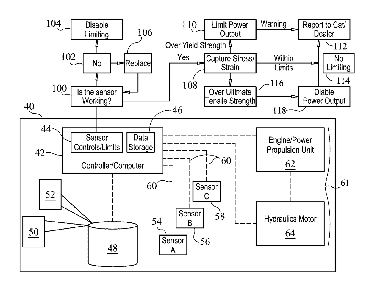
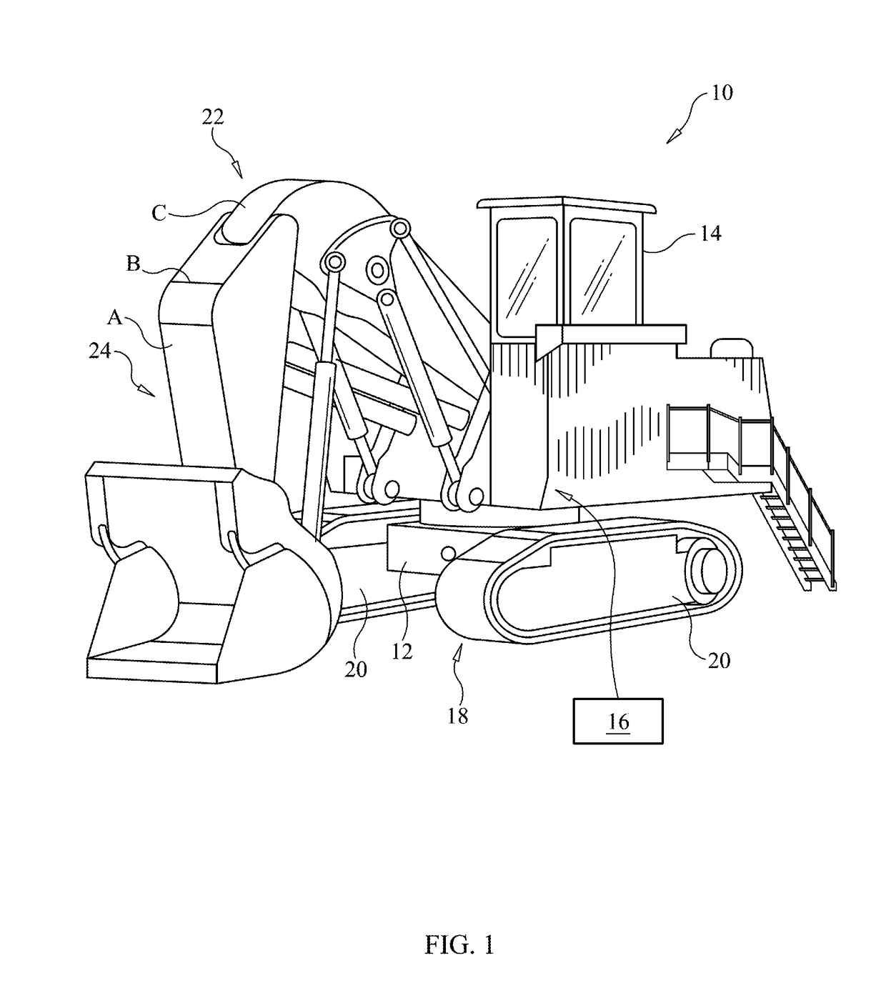
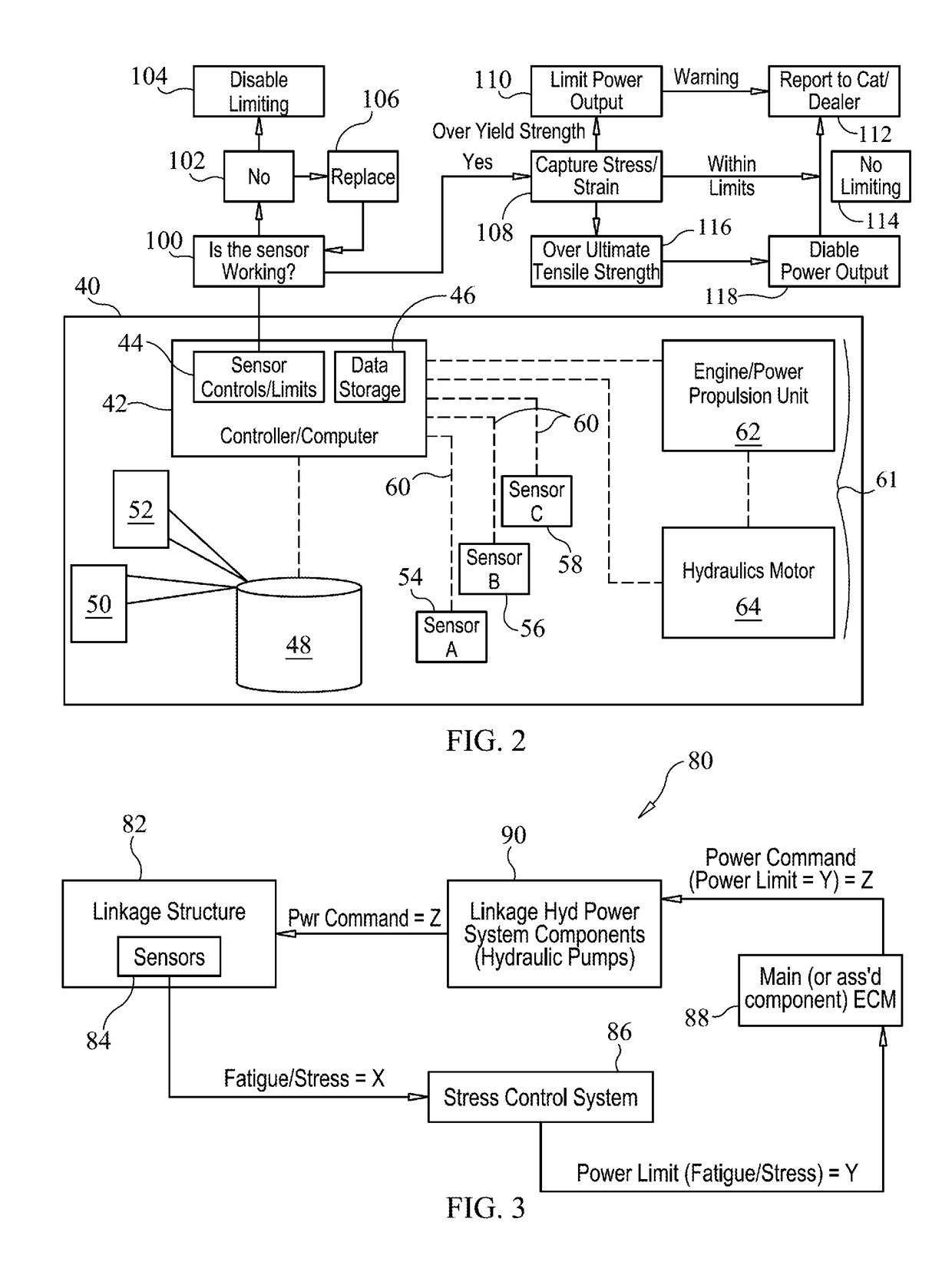
[0011]An exemplary machine, according to the present disclosure, is shown generally at 10. The machine 10 includes a machine frame 12 supporting various machine systems and components, including, for example, an operator control station 14, an engine 16, and a propulsion system 18, including ground engaging propulsion elements 20. The machine 10 may also include a hydraulic power system 22, which may be powered by the engine 16 and used to, in turn, power the propulsion system 18 and / or an implement or tool 24 of the machine 10. Additionally, or alternatively, the machine 10 may include a mechanical power system or an electro-mechanical power system. Turning now to FIG. 2, the machine 10 may also include an electronic control system 40, including an electronic controller 42, for electronically monitoring and controlling the various machine systems and components.

[0012]The electronic controller 42 may be of standard design and may include a processor 44, such as, for example, a centr...


PUM

PropertyMeasurementUnit
degree of stress-strainaaaaaaaaaa
stress-strainaaaaaaaaaa
degrees of stress-strainaaaaaaaaaa

Abstract

A power limiting stress-strain monitor system for a machine includes at least one stress-strain sensor supported on a structural component of the machine. The power limiting stress-strain monitor system also includes an electronic controller including a processor and a memory. The processor receives a signal from the stress-strain sensor, determines a degree of stress-strain at a location of the stress-strain sensor based on the signal, identifies a machine system associated with the stress-strain, and modifies a control signal to the machine system based on the degree of stress-strain.

Description

TECHNICAL FIELD[0001]The present disclosure relates generally to a power limiting stress-strain monitor system, and more particularly to a system and method for identifying a structural stress-strain on a machine and modifying power to avoid or slow occurrence of a structural failure.BACKGROUND[0002]Heavy equipment typically operates in harsh environments, including rugged terrain. As a result of this, and the operating conditions of the equipment, the structural components of the equipment are often subject to stress-strain. Certain machine systems, such as hydraulic power systems, mechanical power systems, and electro-mechanical power systems, for example, may generate movements and forces that contribute to stress-strain in particular areas, such as portions of the machine frame, of the equipment. Over time, the stress-strain may progress and potentially lead to structural failure. A failure can result in significant costs, particularly associated with down-time of the equipment....

Claims


Application Information

Patent Timeline
Patent Type & Authority Applications(United States)
IPC IPC(8): E02F9/24G01L5/00E02F9/20E02F9/26E02F3/30
CPCE02F9/24G01L5/0061E02F3/308E02F9/2058E02F9/268E02F9/2025
Inventor BEHMLANDER, MATTHEWHAMMAR, JEREMY ROE
Owner CATERPILLAR INC
Why Eureka
Try Eureka