Deterministic timing evaluation

a timing evaluation and deterministic technology, applied in the field of deterministic timing evaluation, can solve problems such as the negative influence of system design

Inactive Publication Date: 2018-06-21
HAMILTON SUNDSTRAND CORP
View PDF2 Cites 3 Cited by
  • Summary
  • Abstract
  • Description
  • Claims
  • Application Information

AI Technical Summary

Problems solved by technology

When certain conditions result in an artificial or inconsistent improvement in the WCET, the system design can be negatively affected.

Method used


Image

  • Deterministic timing evaluation
  • Deterministic timing evaluation
  • Deterministic timing evaluation

Examples


Embodiment Construction

[0009]A detailed description of one or more embodiments of the disclosed apparatus and method are presented herein by way of exemplification and not limitation with reference to the Figures.

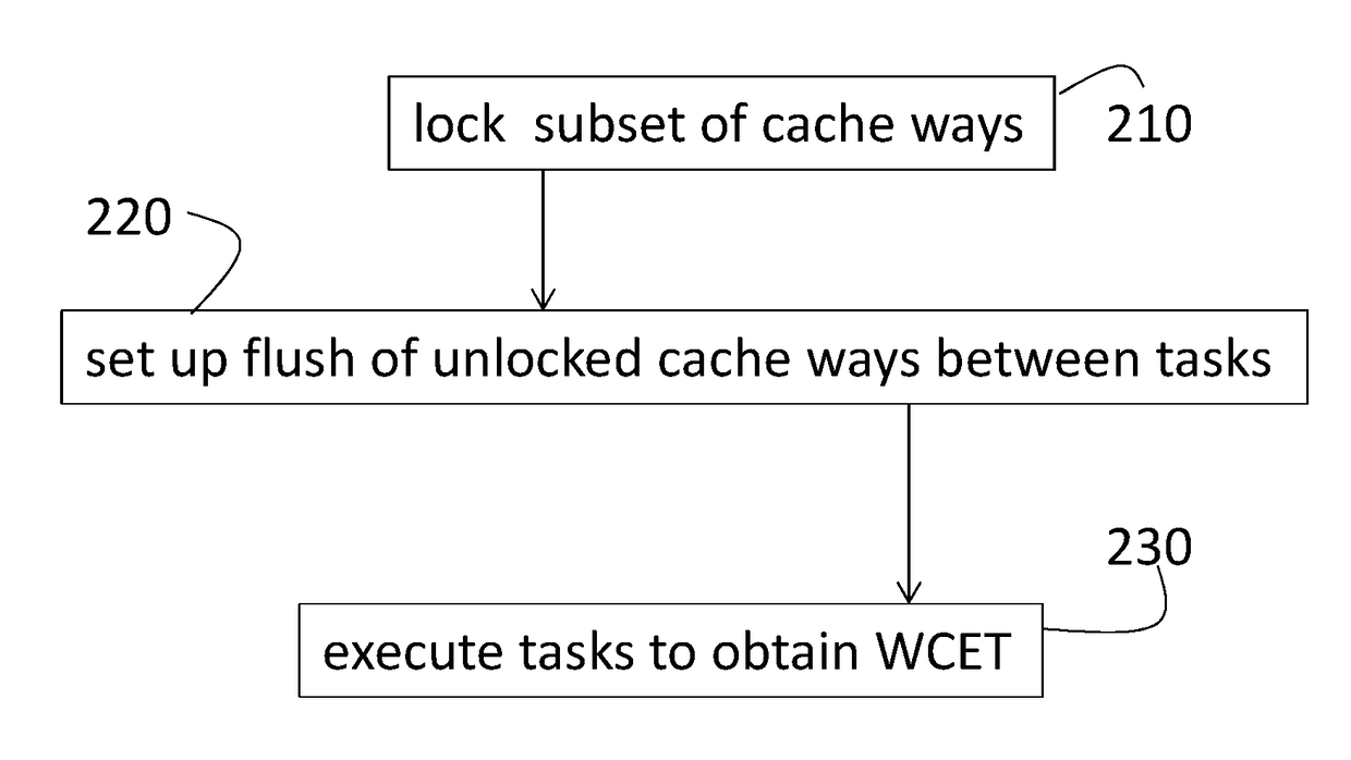
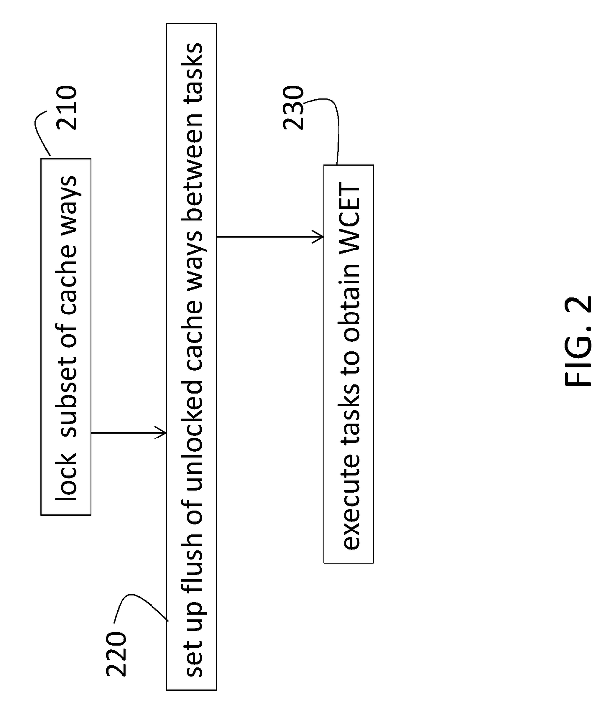
[0010]As previously noted, WCET is one of the parameters that must be determined accurately in order to ensure that a system design meets timing and performance requirements. Embodiments discussed herein specifically refer to an avionic system and, more specifically, a time and space partition real-time operating system (RTOS) for explanatory purposes. The time and space partition RTOS refers to a grouping of certain programs or tasks into each of a number of partitions. The tasks within a given partition are subject to similar certification in the avionics field, for example. Each partition is assigned a portion of available memory space and time. However, the systems and methods detailed herein are not limited to any particular application or to only a partitioned RTOS.

[0011]In the exemplary av...


PUM


Abstract

A method and system to perform deterministic timing analysis of a plurality of software tasks involves cache memory that is shared by the plurality of software tasks. Real memory is accessible by the plurality of software tasks. A task scheduler establishes a cache flush between executions of consecutive tasks among the plurality of software tasks. The cache flush includes movement of data in the cache memory to the real memory. A processor executes the plurality of software tasks to obtain a worst case execution time (WCET) associated with each of the plurality of software tasks.

Description

BACKGROUND[0001]Exemplary embodiments pertain to the art of evaluating execution time of a system processed by a real-time operating system (RTOS).[0002]The design of systems that are implemented with hardware, software, and firmware includes establishing and ensuring compliance with timing and performance constraints. Accordingly, an accurate worst case execution time (WCET) must be established for the execution of software applications, for example. When certain conditions result in an artificial or inconsistent improvement in the WCET, the system design can be negatively affected.BRIEF DESCRIPTION[0003]Disclosed is a system to perform deterministic timing analysis of a plurality of software tasks. A cache memory that is shared by the plurality of software tasks. Real memory accessible by the plurality of software tasks. A task scheduler establishes a cache flush between executions of consecutive tasks among the plurality of software tasks. The cache flush includes movement of dat...

Claims


Application Information

Patent Timeline
Patent Type & Authority Applications(United States)
IPC IPC(8): G06F12/0804
CPCG06F12/0804G06F2212/173G06F2212/1016G06F12/0866G06F12/12
Inventor FRUECHTENICHT, BRIANLEIBHAM, TERRENCE R.PEREIRA, ALEXSCHMIDT, JEFFERY S.KRISHNAKUMAR, BALAJI
Owner HAMILTON SUNDSTRAND CORP
Why Eureka
Try Eureka