
System and method for an optimized operation of real-time embedded solutions in industrial automation

a real-time embedded solution and optimization method technology, applied in the field of real-time embedded solution optimization system and optimization method, can solve the problems of increasing production costs, increasing production costs, and calculating the time a piece or segment of code is going to take to execute, and achieving the effect of improving production efficiency and efficiency

Active Publication Date: 2019-11-05
ABB (SCHWEIZ) AG
View PDF14 Cites 0 Cited by
  • Summary
  • Abstract
  • Description
  • Claims
  • Application Information

AI Technical Summary

Benefits of technology

The patent describes a method and system for optimizing the operation of real-time control applications in industrial automation. The method involves identifying and processing recurring code sequences in control applications to determine their execution time. Using this information, timing data structures are generated for each control application to determine their execution time. These timing data structures are then used to generate a timing model that predicts the best-case and worst-case execution times of the control application. The system includes a data processing unit, a database for storing execution time information, and an interface for inputting data. The system also includes an initial timing model generation unit, a refinement unit, a comparison unit, and an analyzing unit. The technical effect of this patent is to improve the efficiency and accuracy of real-time control applications in industrial automation.

Problems solved by technology

The computation modules and / or processing units for example in most cases are available in different performance levels which relate to the number and complexity of computations they can perform, but more powerful computation modules cause or specify higher technical efforts (design, cooling, environmental conditions or specifications) and higher failure rates in production and finally are more expensive in production as well as in use.
However, according to complexity and for cost and / or effort reasons it is very desirable to use cheapest and / or simplest computation module and / or processing units which can execute the respective task.
Calculating the time a piece or segment of code is going to take to execute has always been a difficult problem.
In most cases, it is impossible as it relates to the halting problem which is indeterminable.
In practice, these specifications cannot always be fulfilled and therefore the WCET might be under-approximated.
For systems with hard real-time specifications, like control systems in automation industry or process industry, this is unsound and potentially unsafe.
This is a long and costly process.
The abstraction underlying the model approximates the execution time in a conservative fashion, thereby leading to an over-approximation of the actual WCET.
In such systems, the diversity of hardware components and / or configurations makes it impractical and almost impossible to manually develop a new static timing model for every possible target platform or target platform configuration.
Moreover, software or applications for safety critical systems commonly have become very large including a tremendous number of code lines, a few million lines of code, and accordingly too large for exhaustive testing.
Thus, it is hazardous to use testing or profiling only, as it is impossible to observe every possible execution of a program to determine the WCET's to provide and ensure a reliable operation of said systems.
Currently, no technical solution is available solving these issues in an efficient way with sufficient quality and minimized technical and / or computational complexity and effort.

Method used


Image

  • System and method for an optimized operation of real-time embedded solutions in industrial automation
  • System and method for an optimized operation of real-time embedded solutions in industrial automation
  • System and method for an optimized operation of real-time embedded solutions in industrial automation

Examples


Embodiment Construction

[0030]Exemplary embodiments of the disclosure provide a solution for an efficient and accurate execution time determination for real time processes to ensure and provide an optimized operation of a control system in automation industry.

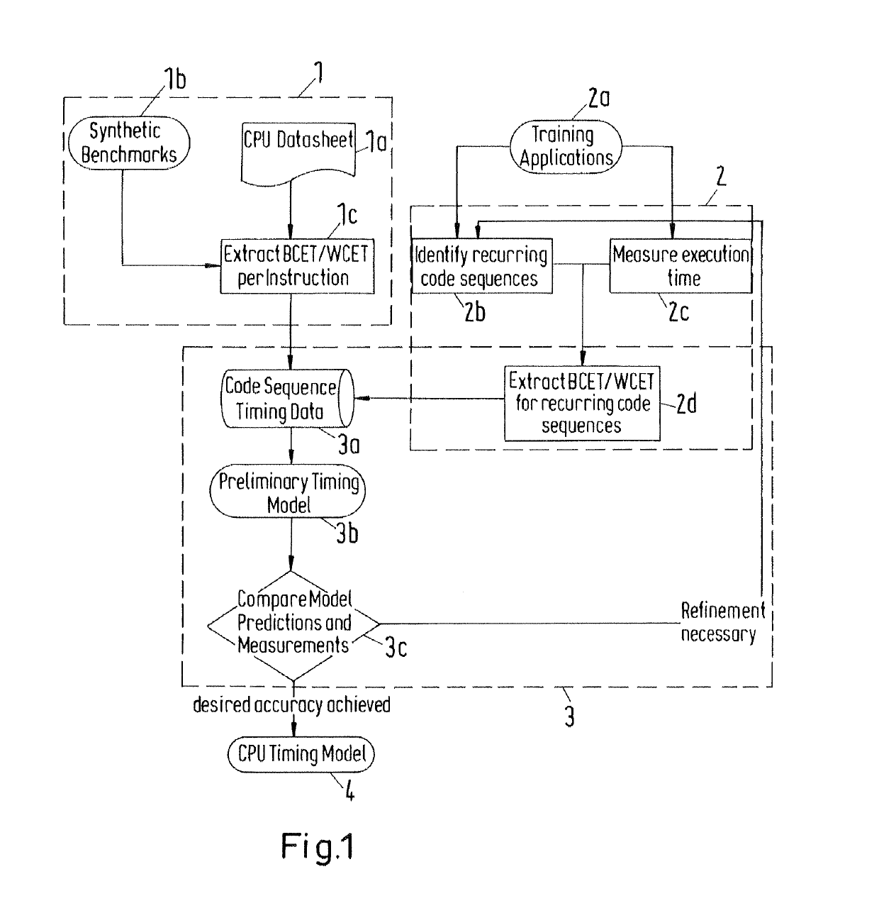
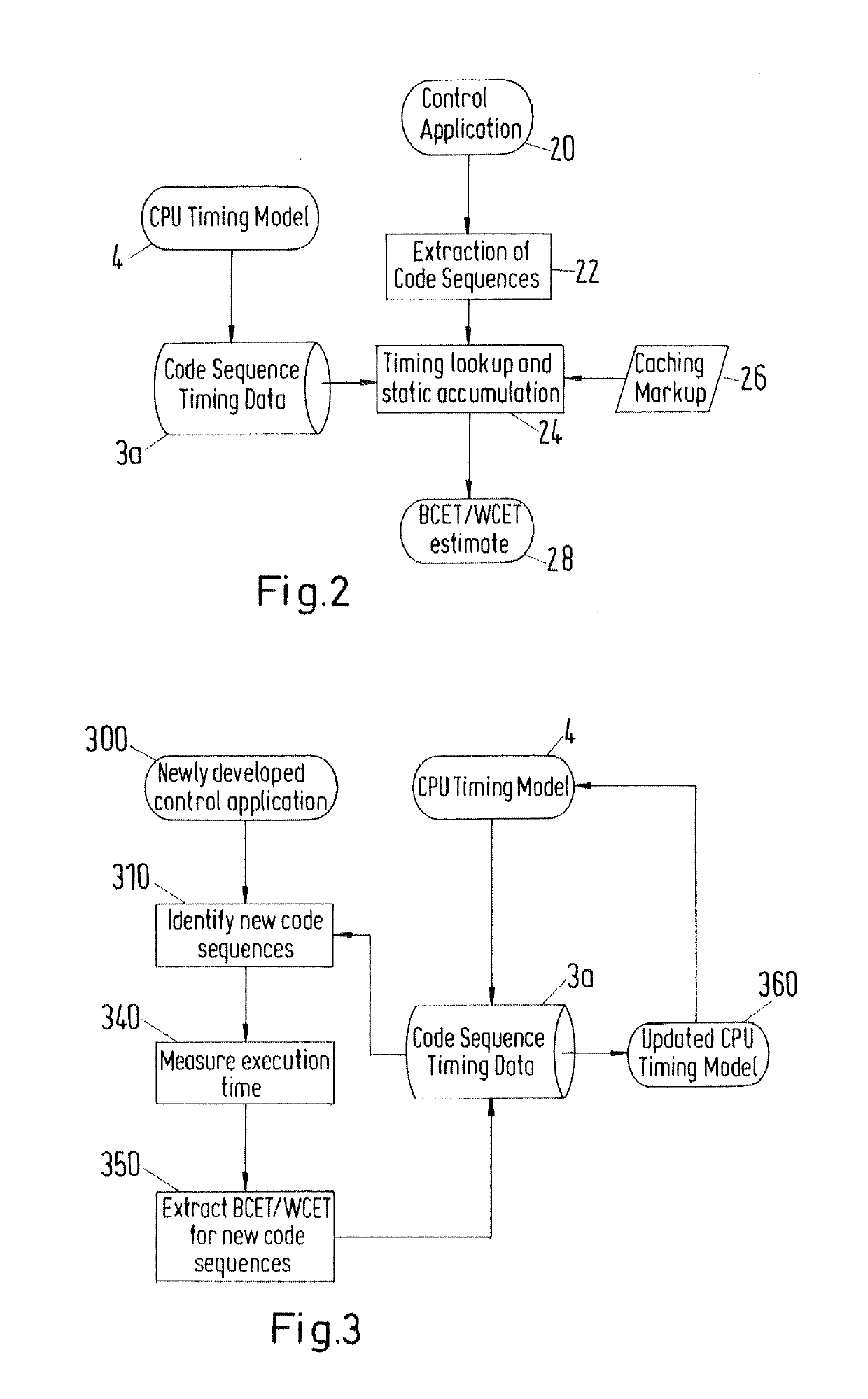
[0031]According to an exemplary embodiment the solution includes a method for an optimized operation of real-time embedded solutions, such as control solutions, in an industrial automation that automatically creates an electronic reproduction of the used control hardware and applies a combination of testing and static analysis to said reproduction to determine the WCET as accurate as possible as a basis for an optimized configuration and operation of said hardware, and a determination and / or selection of suitable processing units for the execution of the respective code segments and the control system.

[0032]A control solution in the context of the present disclosure can be implemented in software or program executed by a processor as well as in hardwa...


PUM


Abstract

A system and method for optimized operation of real-time control applications. The system and method being configured for identifying and processing recurring code sequences in control applications to quantify the execution time of control applications, wherein for each set up and / or control application a timing data structure is generated to determine the execution time of control applications in industrial automation, determining execution times of control applications based on recurring code sequences that are automatically extracted from a set of training applications and / or identified in the respective application, automatically generating test data to determine their on-target execution times for refinement of the timing data structure, decomposing the structure of the respective control application into code sequences for which the created data timing structure and timing model respectively provide execution time estimates, and determining at least an estimate for the best-case execution time and / or the worst-case execution time of the control application.

Description

RELATED APPLICATION(S)[0001]This application claims priority under 35 U.S.C. § 119 to European application 14001258.4 filed on Apr. 4, 2014, the entire content of which is hereby incorporated by reference.FIELD[0002]The disclosure relates to system and method for an optimized operation of real-time embedded solutions, in particular control applications and systems, in industrial automation, wherein for each set up and / or control application a timing data structure is generated to determine the execution time of control applications in industrial automation to ensure and provide an optimized real time operation of the respective industrial control solution.BACKGROUND INFORMATION[0003]When a new automation system or plant is designed, the control application is also developed. Many application components are taken from domain-specific application libraries, for example for oil & gas or the chemical industry. Thus, these components are available from the beginning of the design, but ot...

Claims


Application Information

Patent Timeline
Patent Type & Authority Patents(United States)
IPC IPC(8): G05B19/042G05B11/01G05B19/05
CPCG05B11/01G05B19/0428G05B19/058G05B2219/24036G05B2219/14065G05B2219/24015
Inventor STATTELMANN, STEFANORIOL, MANUEL
Owner ABB (SCHWEIZ) AG
Learn More