
Method and apparatus for monitoring and controlling laser-induced tissue treatment

a technology of laser-induced tissue and monitoring and control, which is applied in the direction of optical elements, instruments, and therapy, can solve the problems of undertreatment or overtreatment of the tissue, requiring strict precision in positioning the handpiece and application of controlled movemen

Active Publication Date: 2005-07-14
HITACHI LTD +1
View PDF50 Cites 126 Cited by
  • Summary
  • Abstract
  • Description
  • Claims
  • Application Information

AI Technical Summary

Benefits of technology

The present invention provides improved methods and apparatus for controlling light-induced tissue treatment that overcome many of the shortcomings of prior art techniques. The invention allows for real-time control of the light beam operational parameters, resulting in greater safety, efficiency, and uniformity of treatment. The invention also monitors and automatically controls in real-time the output optics of the handpiece, delivering the light beam in a controlled discontinuous pattern to a plurality of discrete treatment zones with minimum collateral damage to the intentionally untreated tissue. The invention provides uniform light beam fluence and patterns regardless of the individual target tissue properties and the handpiece velocity. The detector may include an image-processing element, an accelerometer, an optical detector array, a capacitive sensor array, or a profilometer. The handpiece may include a refractive or diffractive focusing element, and various delivery mechanisms may be used. The invention also includes a means for sound, vibration, or visual feedback to help a physician maintain handpiece movement in a predetermined range. Overall, the invention provides a more precise and efficient technique for controlled tissue treatment.

Problems solved by technology

Conversely, improper selection of the optical operational parameters can result in undertreatment or overtreatment of the tissue.
However, as will be discussed in greater detail below, application of these devices have significant disadvantages.
One disadvantage of some of the existing handpiece apparatuses is that they require strict precision in positioning of the handpiece and application of controlled movement in order to stay within limits of safe, uniform and efficacious treatment.
In a real procedure, however, manual application and control of the handpiece can easily result in non-uniformity of treatment due to imprecise or involuntary movements of the human hand and / or uneven tissue surfaces.
This often results in either some areas of the targeted tissue being under-treated, or causes some areas to be over-treated.
Such an approach has the disadvantage of producing artifacts and sharp boundaries associated with the inaccurate positioning of the individual treatments with respect to the treated skin surface.
Another disadvantage of known handpieces is that, as discussed- above, the laser operational parameters defining the selected level of treatment are typically pre-set once for the entire course of treatment.
The disadvantage of this apparatus is that it restricts the physician to a single treatment speed.
Restricting the physician to a pre-selected rate of motion limits the flexibility of the physician when treating regions, such as the face, that include both large flat areas and highly contoured areas that are in close proximity.
Additionally, if the speed of the handpiece changes during the treatment procedure, the apparatus does not provide for automatic adjustment of its operational parameters to compensate for the changed rate of movement, leading to uneven treatment.
However, one disadvantage of typical conventional robotic apparatuses is that they lack the necessary direction and judgment in treatment that a physician provides.
Although robotics is precise, it is not typically intelligent enough to make complex choices or react to unforeseen circumstances during treatment.
Additionally, robots deprive a physician of discretion in an aesthetic sense.
Another disadvantage of the typical conventional robotic apparatus is that the full treatment may require complete immobilization of the patient.
It is still another disadvantage of such robotic apparatuses that they are bulky and cannot be easily moved into treatment positions in relation to the areas allowing little room for movement.

Method used


Image

  • Method and apparatus for monitoring and controlling laser-induced tissue treatment
  • Method and apparatus for monitoring and controlling laser-induced tissue treatment
  • Method and apparatus for monitoring and controlling laser-induced tissue treatment

Examples


Embodiment Construction

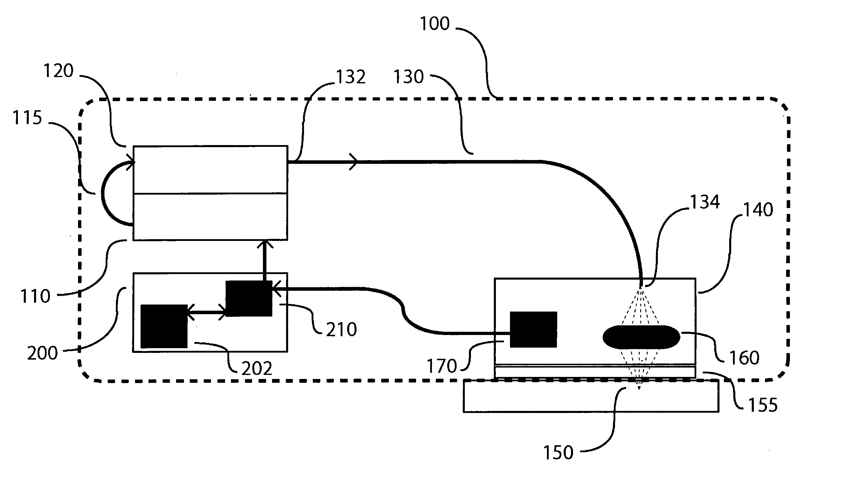
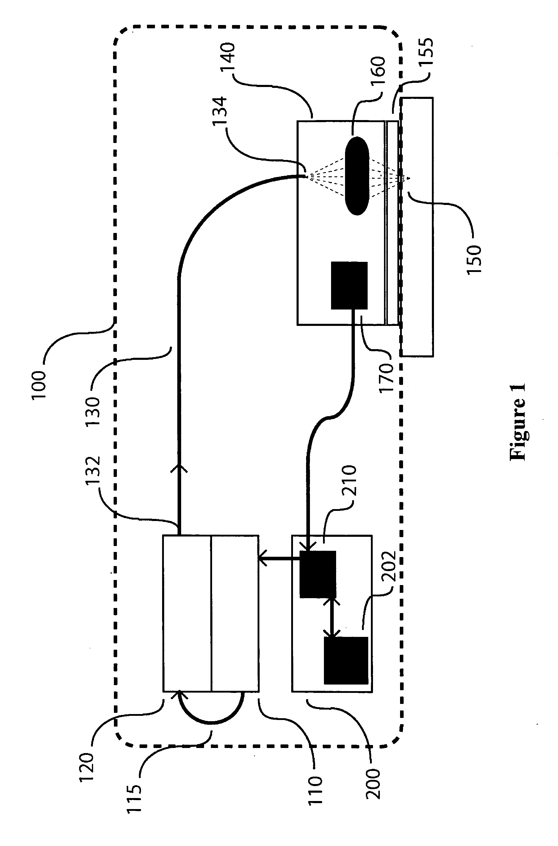
[0041]FIG. 1 illustrates a laser apparatus for controlled tissue treatment 100 in accordance with the present invention. Tissue may include skin tissue as well as other tissues throughout a living body. Various embodiments and examples described herein may refer to skin treatment, but it is understood by those skilled in the art that other tissues can be treated similarly.

[0042] In accordance with the exemplary embodiment shown in FIG. 1, apparatus 100 comprises power source 110 that energizes light emitter 120 for emission of a light beam via an electrical or optical connection 115; optical fiber 130 for transmission of the light beam; movable handpiece 140 with optical element 160 coupled to optical fiber 130 for emission of the light beam towards target area 150; detector 170 for detecting variations in positional parameters of handpiece 140; and controller 200 for controlling operational parameters of the light beam emitted towards target area 150 in response to the detected va...


PUM


Abstract

The present invention provides methods and apparatus for controlling light-induced tissue treatment. In accordance with various aspects of the present invention, the invention provides for improved, real-time control of the light beam operational parameters which enables greater safety, efficiency, uniformity and continuity of the treatment process.

Description

CROSS-REFERENCE TO RELATED APPLICATION [0001] This application is a continuation-in-part of U.S. patent application Ser. No. 10 / 745,761, “Method and Apparatus for Monitoring and Controlling Laser-Induced Tissue Treatment,” filed Dec. 23, 2003; and is also a continuation-in-part of U.S. patent application Ser. No. 10 / 750,790, “High Speed, High Efficiency Optical Pattern Generator Using Rotating Optical Elements,” filed Dec. 31, 2003; and also claims priority under 35 U.S.C. § 119(e) to U.S. Provisional Patent Application Ser. No. 60 / 602,092, “Method and Apparatus for Monitoring and Controlling Laser-Induced Tissue Treatment,” filed Aug. 26, 2004. All of the foregoing are incorporated herein by reference.FIELD OF THE INVENTION [0002] The present invention relates to a method and apparatus for dermatological tissue treatment, and more particularly, to a method and apparatus comprising a combination of a light source, a handpiece, and a means for measurement of the handpiece motion util...

Claims


Application Information

Patent Timeline
Patent Type & Authority Applications(United States)
IPC IPC(8): A61B17/00A61B18/20G02B17/08
CPCA61B18/20A61B18/203A61B2018/2085A61B2018/00452A61B2018/00904A61B2017/00057A61B2018/20351A61B18/22A61N5/0616A61N2005/0626A61N2005/0644A61B2018/00839A61N5/067A61B2018/207
Inventor DEBENEDICTIS, LEONARD C.MYERS, THOMAS R.CHAN, KIN F.FRANGINEAS, GEORGE
Owner HITACHI LTD
Learn More