Memory device with synchronized output path

a memory device and output path technology, applied in the direction of digital transmission, generating/distributing signals, instruments, etc., can solve the problems of phase delay in the external clock signal produced by the memory device, timing problems for other devices,

Inactive Publication Date: 2002-09-03
ROUND ROCK RES LLC
View PDF3 Cites 119 Cited by
  • Summary
  • Abstract
  • Description
  • Claims
  • Application Information

AI Technical Summary

Problems solved by technology

Due to internal delays associated with the components of the memory device, the phase of the external clock signal is shifted within the memory device, such the output data delivered from the device is no longer exactly aligned with the external clock signal.
In such an arrangement, the phase delay in the external clock signal produced by the memory device becomes problematic.
Such an arrangement generates timing problems for other devices accessing the memory device.

Method used


Image

  • Memory device with synchronized output path
  • Memory device with synchronized output path
  • Memory device with synchronized output path

Examples


Embodiment Construction

Illustrative embodiments of the invention are described below. In the interest of clarity, not all features of an actual implementation are described in this specification. It will of course be appreciated that in the development of any such actual embodiment, numerous implementation-specific decisions must be made to achieve the developers' specific goals, such as compliance with system-related and business-related constraints, which will vary from one implementation to another. Moreover, it will be appreciated that such a development effort might be complex and time-consuming, but would nevertheless be a routine undertaking for those of ordinary skill in the art having the benefit of this disclosure.

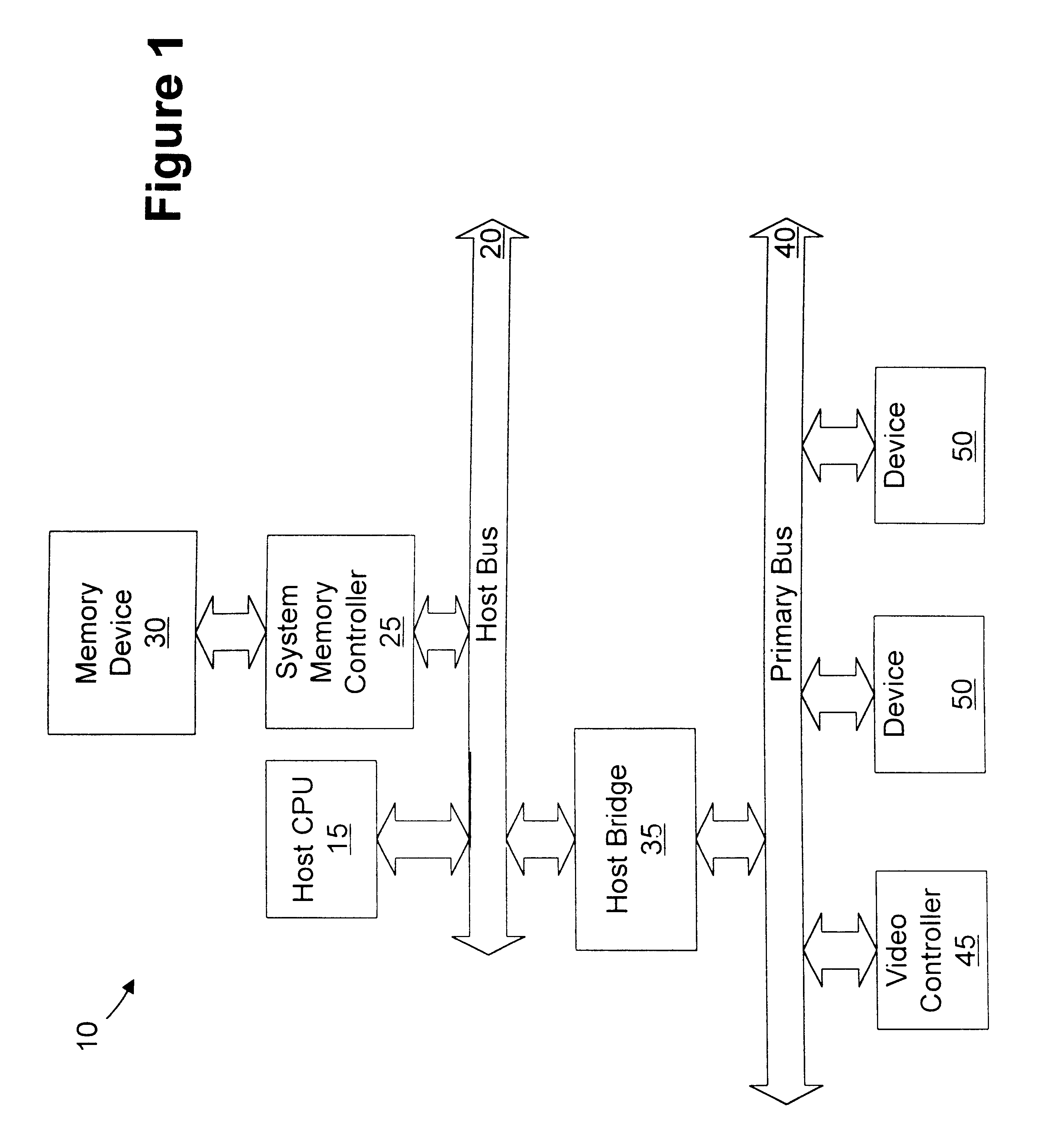
Referring to FIG. 1, a simplified block diagram of a computer system 10 is provided. The computer system 10 includes a microprocessor 15, which may include multiple processors (not shown) coupled to a host bus 20. A system memory controller 25 is coupled to the host bus and a memory de...


PUM


Abstract

A memory device includes a data array, array control logic, a delay locked loop circuit, timing control logic, and a first storage device. The array control logic is adapted to receive a read command synchronized with an external clock signal and to read at least a first data element from the data array based on the read command. The delay locked loop circuit is adapted to receive the external clock signal and delay the external clock signal by a programmable amount to generate a delay locked loop clock signal. The timing control logic is adapted to generate a first input enable signal based on the external clock signal and a first output enable signal based on the delay locked loop clock signal. The first storage device adapted to receive the first data element. The first storage device has an input terminal enabled in response to the first input enable signal and an output terminal enabled in response to the first output enable signal.

Description

1. Field of the InventionThis invention relates generally to synchronous memory devices, and, more particularly, to a synchronous memory device adapted to receive input data and provide output data synchronized with a common external clock signal.2. Description of the Related ArtMemory devices, such as synchronous dynamic random access memories (SDRAM) have been widely used to enhance the performance of computer systems executing memory intensive applications. Synchronous memory devices receive and deliver data coincident with a clock signal. In previous SDRAM devices, an external clock signal is received by the device. Input signals and data are received synchronized with the external clock signal. Due to internal delays associated with the components of the memory device, the phase of the external clock signal is shifted within the memory device, such the output data delivered from the device is no longer exactly aligned with the external clock signal. A typical SDRAM can read or ...

Claims


Application Information

Patent Timeline
Patent Type & Authority Patents(United States)
IPC IPC(8): G06F13/42
CPCG06F13/4243
Inventor LI, WENMORZANO, CHRISTOPHER K.
Owner ROUND ROCK RES LLC
Why Eureka
Try Eureka