Method and apparatus for characterizing a delay locked loop

a delay and loop technology, applied in the direction of electrical equipment, pulse automatic control, etc., can solve the problems of large differences in the phases of the respective chip generated clocks, insufficient system reference clocks to all components, and skews in data signal transitions,

Inactive Publication Date: 2004-08-10
MICRON TECH INC
View PDF10 Cites 75 Cited by
  • Summary
  • Abstract
  • Description
  • Claims
  • Application Information

AI Technical Summary

Problems solved by technology

The improved performance of computing integrated circuits and the growing trend to include several computing devices on the same board present a challenge with respect to synchronizing the time frames of all the components.
While the operation of all components in the system should be highly synchronized, i.e., the maximum skew in time between the significant edges of the internally generated clocks of all the components should be minimized, it is not enough to feed the reference clock of the system to all the components.
This is because different chips may have different manufacturing parameters, which, when taken together with additional factors such as ambient temperature, voltage, and processing variations, may lead to large differences in the phases of the respective chip generated clocks.
However, because the DDLL is implemented using digital circuitry, it must make discrete delay adjustments to attempt to synchronize the data transitions with the reference clock signal.
Because of this granularity, there is typically some degree of skew between the reference clock signal and the transitions of the data signal.
If the device is unable to keep the data transitions within the predetermined tolerances, other devices may receive errant data (i.e., data that is still transitioning when it is expected to be stable).
There are limitations to the accuracy of the tAC characterization performed using the back-end test methodology described above.
Variations in the process, voltage, and temperature (i.e., PVT variations) can cause changes in the performance of the DDLL, because they affect the delay imposed by the delay line.
For example, increases in temperature may increase the delay imposed by the delay line.
Because parameters such as voltage and temperature are not varied during the test, it is possible that the tester does not accurately characterize the worst case tAC.
Such a characterization in the lab is time consuming and not practical for back-end testing of large numbers of devices.
This inaccurate characterization may lead to passing devices that are actually not within design tolerances.
Characterization errors may also result in incorrect decisions regarding which DLL trim fuses should be blown to move the entire tAC window and tune the DDLL.
If the actual tAC is different than the back-end characterization, the window may be shifted too far or even in the wrong direction.
Such an errant tuning could cause a device that was initially within design tolerances to be moved to a region where it is actually outside of these tolerances.
A phase alignment error between the input clock signal and the feedback clock signal is detected.

Method used


Image

  • Method and apparatus for characterizing a delay locked loop
  • Method and apparatus for characterizing a delay locked loop
  • Method and apparatus for characterizing a delay locked loop

Examples


Embodiment Construction

Illustrative embodiments of the invention are described below. In the interest of clarity, not all features of an actual implementation are described in this specification. It will of course be appreciated that in the development of any such actual embodiment, numerous implementation-specific decisions must be made to achieve the developers specific goals, such as compliance with system-related and business-related constraints, which will vary from one implementation to another. Moreover, it will be appreciated that such a development effort might be complex and time-consuming, but would nevertheless be a routine undertaking for those of ordinary skill in the art having the benefit of this disclosure.

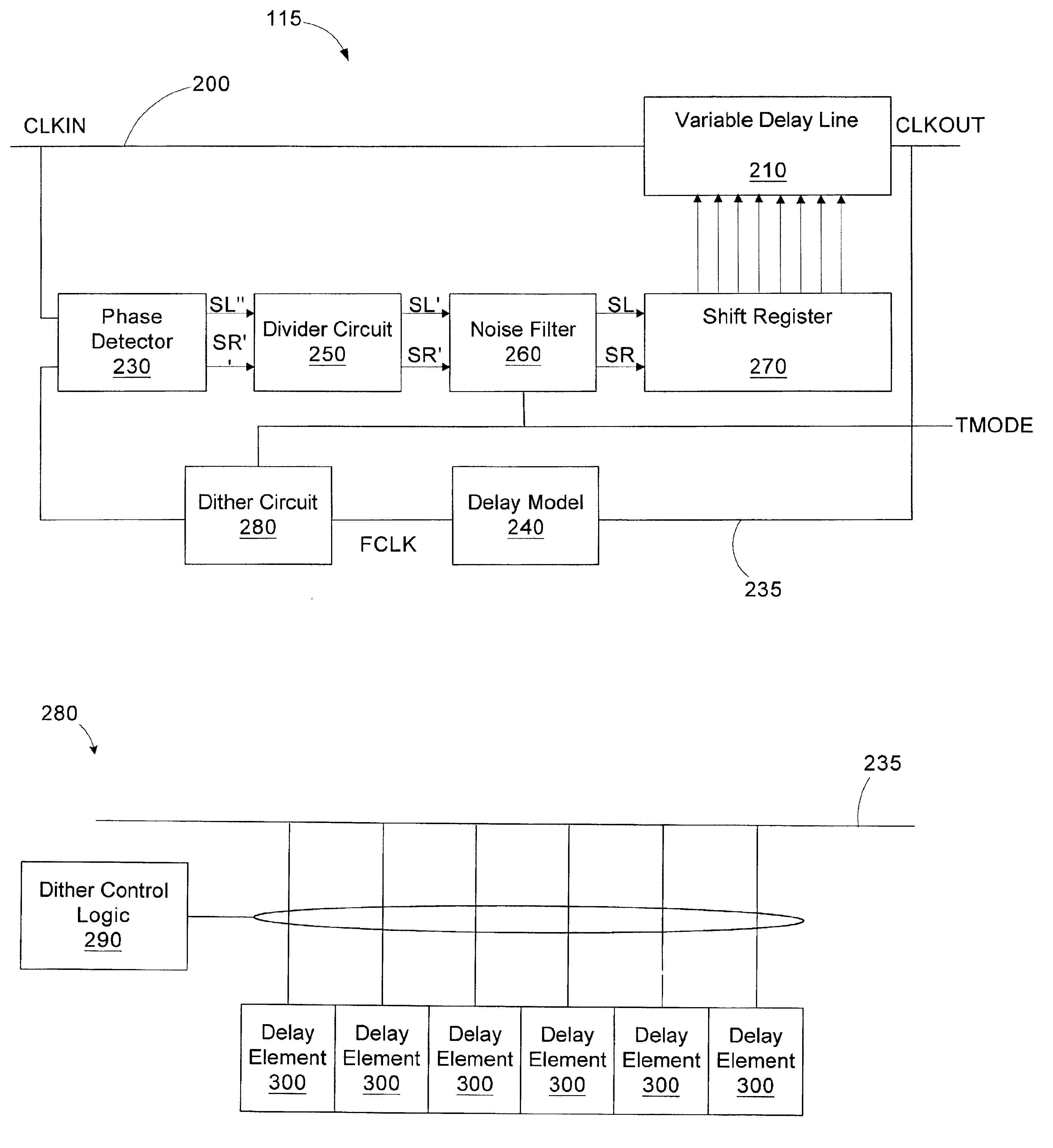
Referring to FIG. 3, a simplified block diagram of a digital system 100 is provided. The digital system 100 includes a first digital device 105 coupled to a second digital device 110. The first digital device 105 provides a reference clock signal (CLKIN) to the second digital device 110...


PUM


Abstract

A delay locked loop includes a forward path, a feedback path, a phase detector, logic, and a dither circuit. The forward path includes a delay line configured to receive an input clock signal and delay the input clock signal by a time interval to generate an output clock signal. The feedback path is configured to provide a feedback clock signal based on the output clock signal. The phase detector is configured to compare the input clock signal and the feedback clock signal and generate a shift signal if the output clock signal is not in phase with the input clock signal. The logic is coupled to the delay line and configured to receive the shift signal and control the time interval based on the shift signal. The dither circuit is coupled to the delay line and configured to introduce a delay responsive to an assertion of a test mode enable signal.

Description

1. Field of the InventionThis invention relates generally to the synchronization of periodic signals, such as clock signals. More particularly, the invention relates to a method and apparatus for characterizing a delay locked loop.2. Description of the Related ArtMany high speed electronic systems possess critical timing requirements that dictate the need to generate a periodic clock waveform possessing a precise timing relationship with respect to some reference signal. The improved performance of computing integrated circuits and the growing trend to include several computing devices on the same board present a challenge with respect to synchronizing the time frames of all the components.While the operation of all components in the system should be highly synchronized, i.e., the maximum skew in time between the significant edges of the internally generated clocks of all the components should be minimized, it is not enough to feed the reference clock of the system to all the compon...

Claims


Application Information

Patent Timeline
Patent Type & Authority Patents(United States)
IPC IPC(8): H03L7/08H03L7/081
CPCH03L7/0814H03L7/0816
Inventor GOMM, TYLER J.ROTH, MICHAEL B.
Owner MICRON TECH INC
Why Eureka
Try Eureka