
Reference timing signal apparatus and method

a timing signal and reference timing technology, applied in the direction of optical radiation measurement, pulse technique, instruments, etc., can solve the problems of base station failure to communicate properly, subject to lightning damage, synchronization jeopardized,

Active Publication Date: 2006-03-21
APPLE INC
View PDF7 Cites 71 Cited by
  • Summary
  • Abstract
  • Description
  • Claims
  • Application Information

AI Technical Summary

Benefits of technology

[0017]It is an object of the present invention to provide improved reference timing signal apparatus and method for providing a timing output signal.
[0031]In a case where the reference timing signal apparatus is applied to a base station, for example, it improves current GPS-based clock stability during holdover by better estimating and compensating for the performance of a crystal used to generate a clock signal during the holdover period. Also, it improves the clock stability during holdover based in other satellite systems, e.g., GLONASS and Galileo.

Problems solved by technology

The GPS receiver antennas of cellular phone equipment are often placed high relative to surrounding terrain and they are subject to lightning damage in addition to physical damage from rough handling or other damage.
This synchronization is jeopardized when the base station fails to receive a GPS signal, and must rely on an oscillator to maintain time independent of the GPS signal still used by neighboring base stations.
This commonly occurs as a result of lightning strikes that damage the GPS antenna or receiver of a CDMA system, and also occurs as a result of damage due to rough handling and vandalism or from other causes.
If the oscillator is not sufficiently stable, the time it provides to the base station may drift with respect to the desired GPS reference time, and cause the base station to fail to communicate properly.
But, because crystals often take from 20 to 30 days to settle in or become stable in performance, this test cannot ensure performance of the crystal in extended operation.
Excessive frequency drift due to molecular settling or spurious frequency jumps due to contaminants in the crystal may cause the crystal to perform much more poorly in the field than these preliminary tests could indicate.
Other factors such as rough handling during installation or spurious mechanical changes in the crystal may further degrade crystal stability, and are not detectable after initial testing.
However, in general, the frequency stability of low cost OCXOs is poor and thus, the frequency stability in the holdover period is not reliable.
It does not address the problem of a low performance reference oscillator.
It does not address the problem of low performance reference oscillator, either.
In order not to have to know the oscillator frequency during the holdover period, the problem is that one of ensuring the cumulative time error of the free running oscillator remains within the specified 6.9 microseconds.
For example, rubidium oscillators and conventional double oven crystal oscillator are still expensive.

Method used


Image

  • Reference timing signal apparatus and method
  • Reference timing signal apparatus and method
  • Reference timing signal apparatus and method

Examples


Embodiment Construction

[0058]In the following detailed description of sample embodiments of the invention, reference is made to the accompanying drawings which form a part hereof, and in which is shown by way of illustration specific sample embodiments in which the invention may be practiced. These embodiments are described in sufficient detail to enable those skilled in the art to practice the present invention, and it is to be understood that other embodiments may be utilized and that logical, mechanical, electrical, and other changes may be made without departing from the scope of the present invention. The following detailed description is, therefore, not to be taken in a limiting sense, and the scope of the present invention is defined only by the appended claims.

[0059]The present invention is applicable to a computer algorithm which adaptively models the multiple frequency dependent characteristics in relation to an oscillator following a “training period”. The subsequent model predicts the future f...


PUM


Abstract

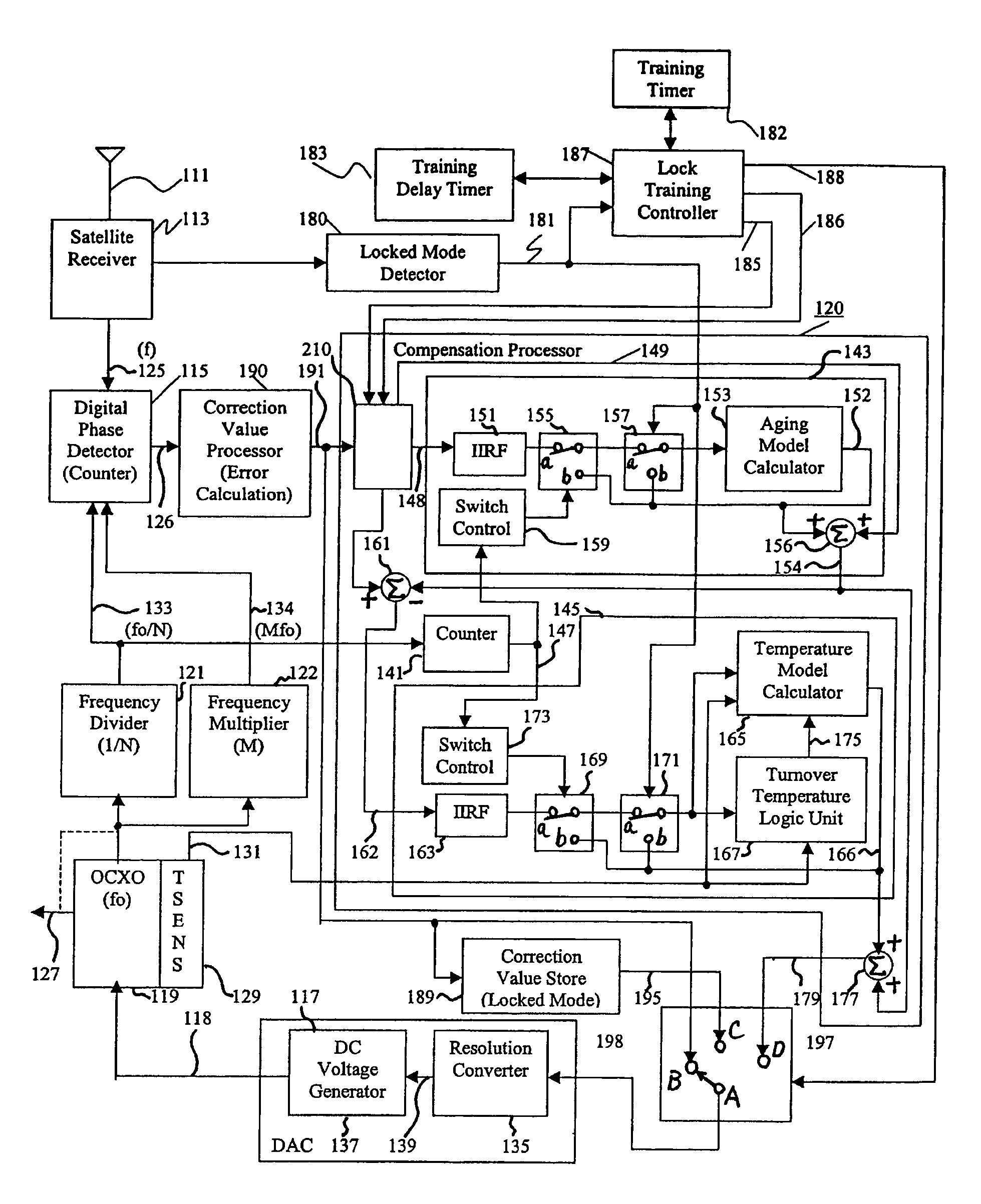
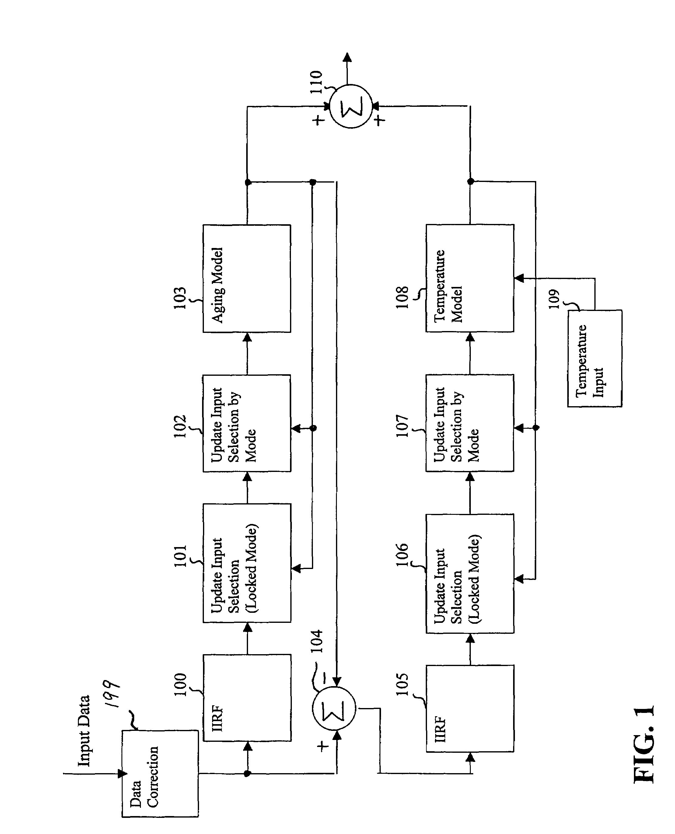
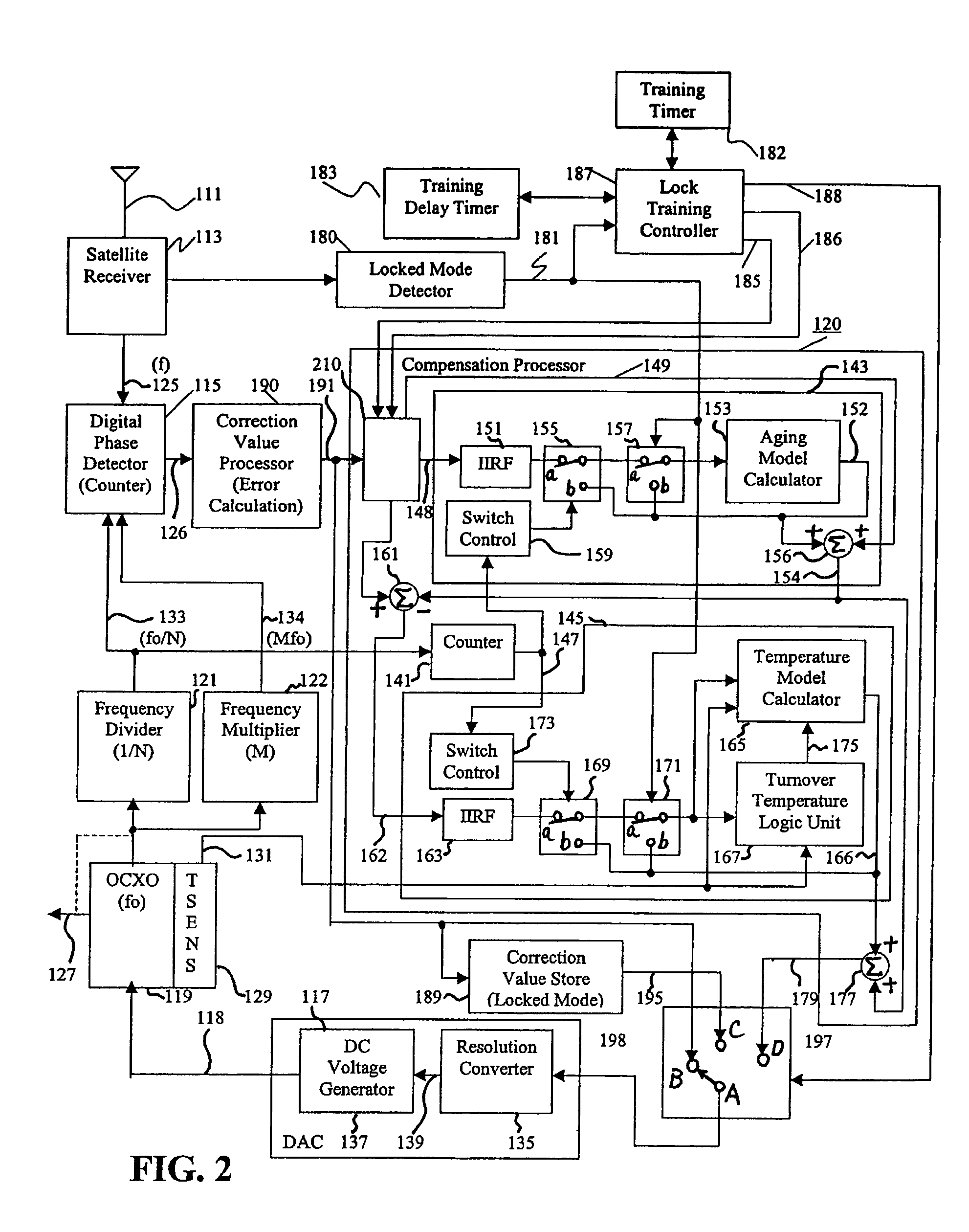
A reference timing signal apparatus with a phase-locked loop (PLL) has a computer algorithm which adaptively models the multiple frequencies of an oscillator following a training period. The oscillator is part of a PLL and the oscillation frequency thereof is controlled in response to the phase detector output. The computer algorithm processes the control signal applied to the oscillator. The computer algorithm updates the characteristics of the model relating to the aging and temperature of the oscillator, using for example, a Kalman filter as an adaptive filter, in accordance with a cumulative phase error in the PLL calculated during a given time interval. By the algorithm, the subsequent model predicts the future frequency state of the oscillator on which it was trained. The predicted frequency of the model functions as a reference to correct the frequency of the oscillator in the event that no input reference timing signal is available. Also, the calculated phase error is stored and is used while no input reference timing signal or accurate predicted frequency value is available. With the model updating algorithm, oscillators of low stability performance may be used as cellular base station reference oscillator, which is based on satellite systems, for example, GPS, GLONASS or Galileo systems.

Description

FIELD OF THE INVENTION[0001]The present invention relates to a reference timing signal apparatus and method for providing a timing output signal. The reference timing signal apparatus is applicable to a cellular telephone base station, for example. The present invention is also applicable to reference signal or clock signal generators in other types of apparatus, for example, optical transport networks.BACKGROUND OF THE INVENTION[0002]A known cellular telephone system is a Code Division Multiple Access (CDMA) system. The CDMA wireless phone system allows multiple cellular phone users to share the same frequency spectrum, and uses a generated noise carrier with a different and essentially orthogonal instance of the noise carrier assigned to each mobile unit within a cell. The base station receiver in a CDMA station correlates the received signal from a mobile unit with the desired noise carrier, extracting the transmitted digital signal with a sufficient signal-to-noise ratio to achi...

Claims


Application Information

Patent Timeline
Patent Type & Authority Patents(United States)
IPC IPC(8): H03L7/00
CPCH03L1/00H03L7/14H03L7/08
Inventor NICHOLLS, CHARLESWU, PHILIPPECARLETON, GREGORYBEAUDIN, STEVE
Owner APPLE INC
Learn More