
Doubly-differential interferometer and method for evanescent wave surface detection

a technology of evanescent wave surface and interferometer, which is applied in the field of optical sensors, can solve the problems of affecting the utility of tagging targets, affecting the detection and/or measurement of desired targets, and difficulty in ensuring that only the target analytes are tagged,

Inactive Publication Date: 2002-01-10
PERFECT GALAXY INT
View PDF0 Cites 74 Cited by
  • Summary
  • Abstract
  • Description
  • Claims
  • Application Information

AI Technical Summary

Benefits of technology

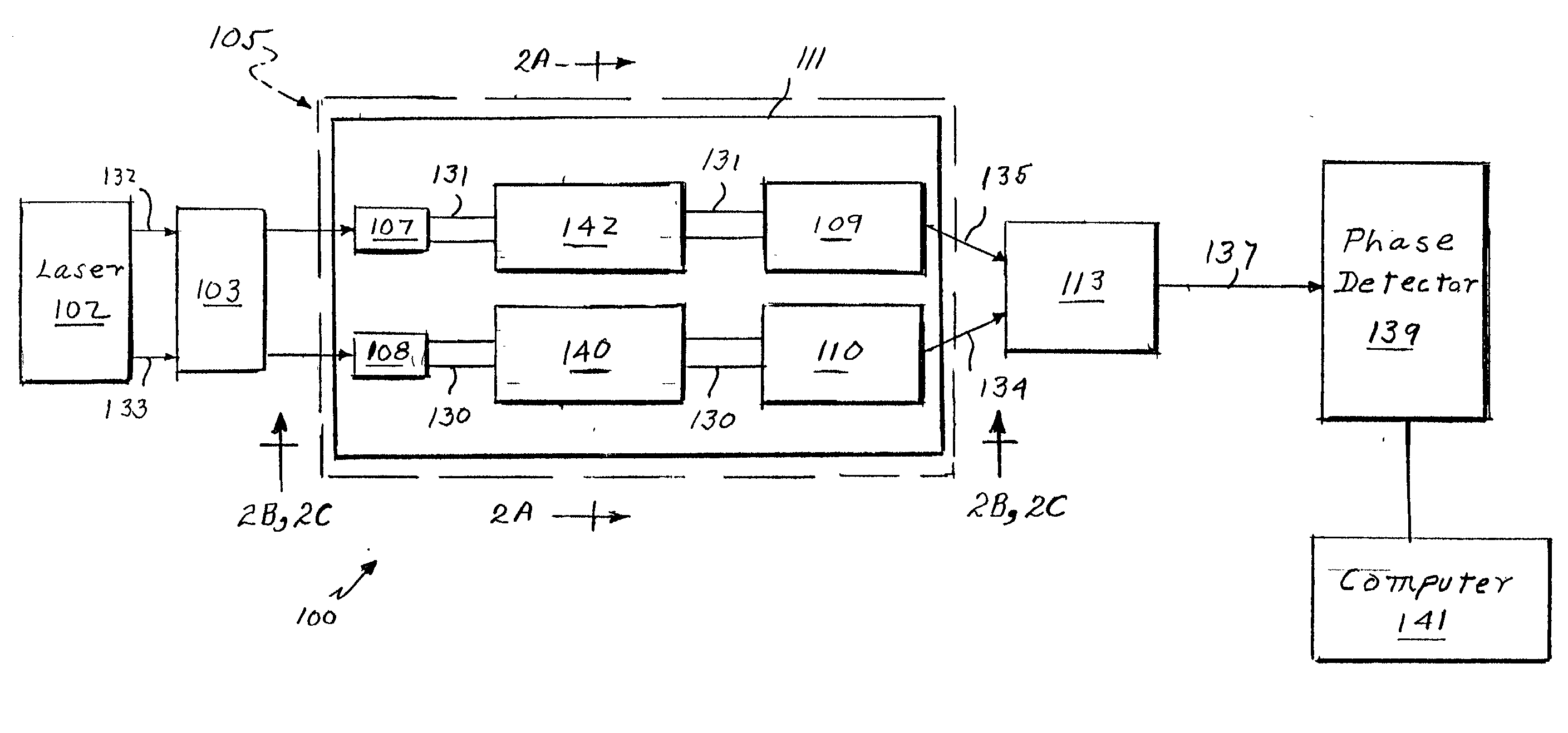
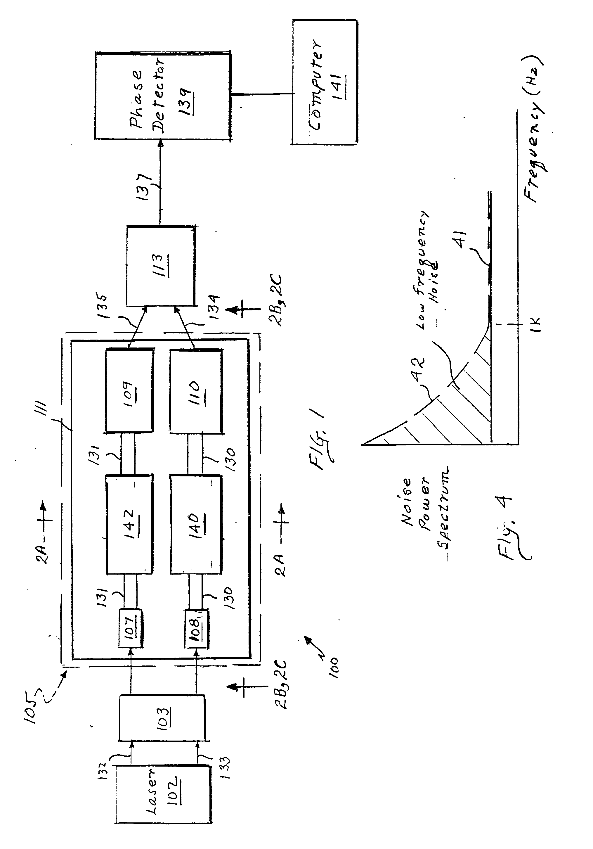
[0018] In a preferred embodiment, light enters a polarization modulator, which facilitates removing low frequency noise signals. The polarization modulator enables exciting two orthogonally polarized spatial, i.e., guided, modes, causing each guided mode to propagate independently and sequentially through the spatially separated measurement and reference optical paths. Subsequently, the light from each path can be coupled out of the waveguide and coherently combined for each polarization mode. An optical phase detector can be used to record any changes in phase for each guided mode and to compare any changes with subsequent measurements. These optical phase changes, typically, are caused by characteristics of the measurement and reference samples and the targets bound thereto, which samples are contiguous to the surface of the waveguide.
[0021] Advantageously, this doubly differential surface detection technique, as implemented on the optical sensing platform of the present invention, provides immunity to environmental effects, such as temperature changes, mechanical vibrations, and biochemical effects, such as non-specific binding, thereby providing the sensitivity and speed required for directly detecting and / or measuring, in real time, very small numbers of bound targets, e.g., small molecules, bio-molecules, and / or microorganisms, including a single target, bound to or contained within the sample.

Problems solved by technology

For example, the expense and complexity of reagents used for tagging the targets affect its utility.
Specifically, it is often difficult to ensure that only the target analytes are tagged.
Frequently, however, random substances bound to the waveguide surface are tagged also, thereby affecting the detection and / or measurement of the desired targets.
Such non-specific binding of random substances can adversely affect, e.g., the signal-to-noise ratio (SNR) of that evanescent wave surface detection technique.
For example, biochemical and environmental factors such as non-specific binding and temperature variation typically limit the sensitivity and stability of that evanescent wave surface detection technique.
Furthermore, the BIAcore.TM. brand SPR instrument is commercially expensive; hence, it is often inappropriate for use in low-cost applications.
For example, this evanescent wave surface detection technique typically lacks the stability required for accurately detecting and / or measuring very small numbers of targets.
This is because the stability of that evanescent wave surface detection technique typically is limited by biochemical and environmental factors, i.e., noise, such as non-specific binding and temperature variation of the bulk liquid, which often result in less than optimal SNR ("signal-to-noise ratio").
Moreover, thermal and mechanical perturbations, which are major sources of noise and which adversely affect the SNR.
Moreover, subtracting temporally adjacent measurements in the reference and measurement samples results in the common-mode rejection of in-band noise.

Method used


Image

  • Doubly-differential interferometer and method for evanescent wave surface detection
  • Doubly-differential interferometer and method for evanescent wave surface detection
  • Doubly-differential interferometer and method for evanescent wave surface detection

Examples


Embodiment Construction

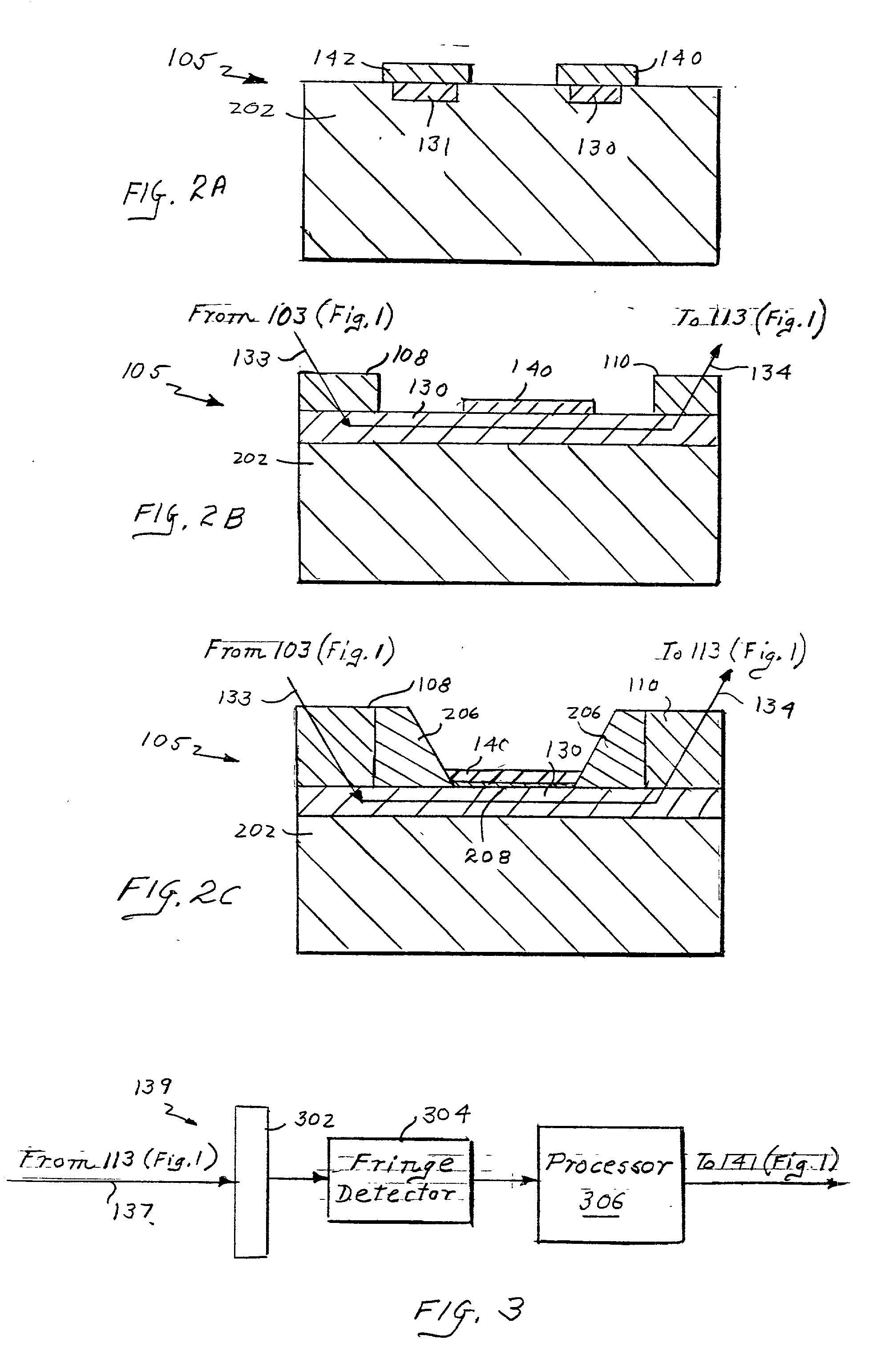
[0032] As shown in FIG. 1, an optical sensing platform 100 in accordance with one embodiment in the present invention includes a light source, e.g., laser 102, a polarization modulator 103, an integrated optical sensor 105, a beam combiner 113, a phase detector 139, and a computer 141.

[0033] The light source, e.g., laser 102, injects beams 132, 133 into a polarization modulator 103. The polarization modulator 103 rotates, or modulates, the polarization of the incident light to enable the excitement of two orthogonally polarized guided modes, e.g., the TE.sub.m (transverse electric) and TM.sub.m (transverse magnetic) modes, in each of the measurement and reference paths 130, 131. Moreover, the polarization modulator 103 causes the two polarized guided modes to propagate sequentially through both the measurement and reference paths 130, 131. The polarization modulator 103 can be of any type that is well known to those of ordinary skill in the art, e.g., a ferro-electric liquid crystal...


PUM

PropertyMeasurementUnit
temporal frequenciesaaaaaaaaaa
frequenciesaaaaaaaaaa
frequencyaaaaaaaaaa

Abstract

A high speed, highly sensitive optical sensing platform and a method for detecting and / or measuring characteristics of a substance in a measurement sample are disclosed. The platform includes at least one pair of optical paths formed in a waveguide, a light source for injecting optical beams along the optical paths, a light modulator for enabling the excitement of a transverse electric and a transverse magnetic guide modes, and a phase detector for detecting phase differences between the beams propagating along the optical paths. One of the optical paths has a target analyte of unknown concentration with a measurement sample bound to its upper surface, while the second optical path has a reference sample containing a known concentration of the target analyte bound to its upper surface. A guided mode modulator causes an optical beam to propagate through the waveguide sequentially as two polarized modes. The highly sensitive platform is especially useful for directly detecting and / or measuring very small numbers of small molecules, bio-molecules, microorganisms in a liquid or gaseous test sample.

Description

CROSS REFERENCE OR RELATED APPLICATIONS[0001] This application claims the benefit of U.S. Provisional Application No. 60 / 188,808 filed Mar. 13, 2000.[0002] 1. Field of the Invention[0003] This invention relates generally to optical sensors, and more particularly to high speed, highly sensitive, optical sensing platforms for evanescent wave surface detection applications, i.e., an evanescent interferometer biosensor.[0004] 2. Discussion of Related Art[0005] Evanescent wave surface detection is an optical technique that has been used in various applications such as the detection of substances in liquid and gaseous samples and the measurement of certain properties of liquid and gaseous samples, including, e.g., changes in refractive indices and ionic concentrations of the samples.[0006] The evanescent wave surface detection technique typically includes sensing a change in the local environment at the surface of a waveguide. The waveguide surface is often coated with a chemically or bio...

Claims


Application Information

Patent Timeline
Patent Type & Authority Applications(United States)
IPC IPC(8): G01N21/45G01N21/77
CPCG01N21/45G01N21/7703G01N2021/7779
Inventor RIEDER, RONALD J.
Owner PERFECT GALAXY INT
Learn More