
Synchronized multi-output digital clock manager

a digital clock manager and multi-output technology, applied in the field of digital clocking circuits, can solve problems such as failure to capture the data from the first, digital systems to malfunction, and the edge of a clock signal in different parts of the system may not be synchronized,

Inactive Publication Date: 2007-03-06
XILINX INC
View PDF23 Cites 72 Cited by
  • Summary
  • Abstract
  • Description
  • Claims
  • Application Information

AI Technical Summary

Benefits of technology

[0017]The present invention will be more fully unde...

Problems solved by technology

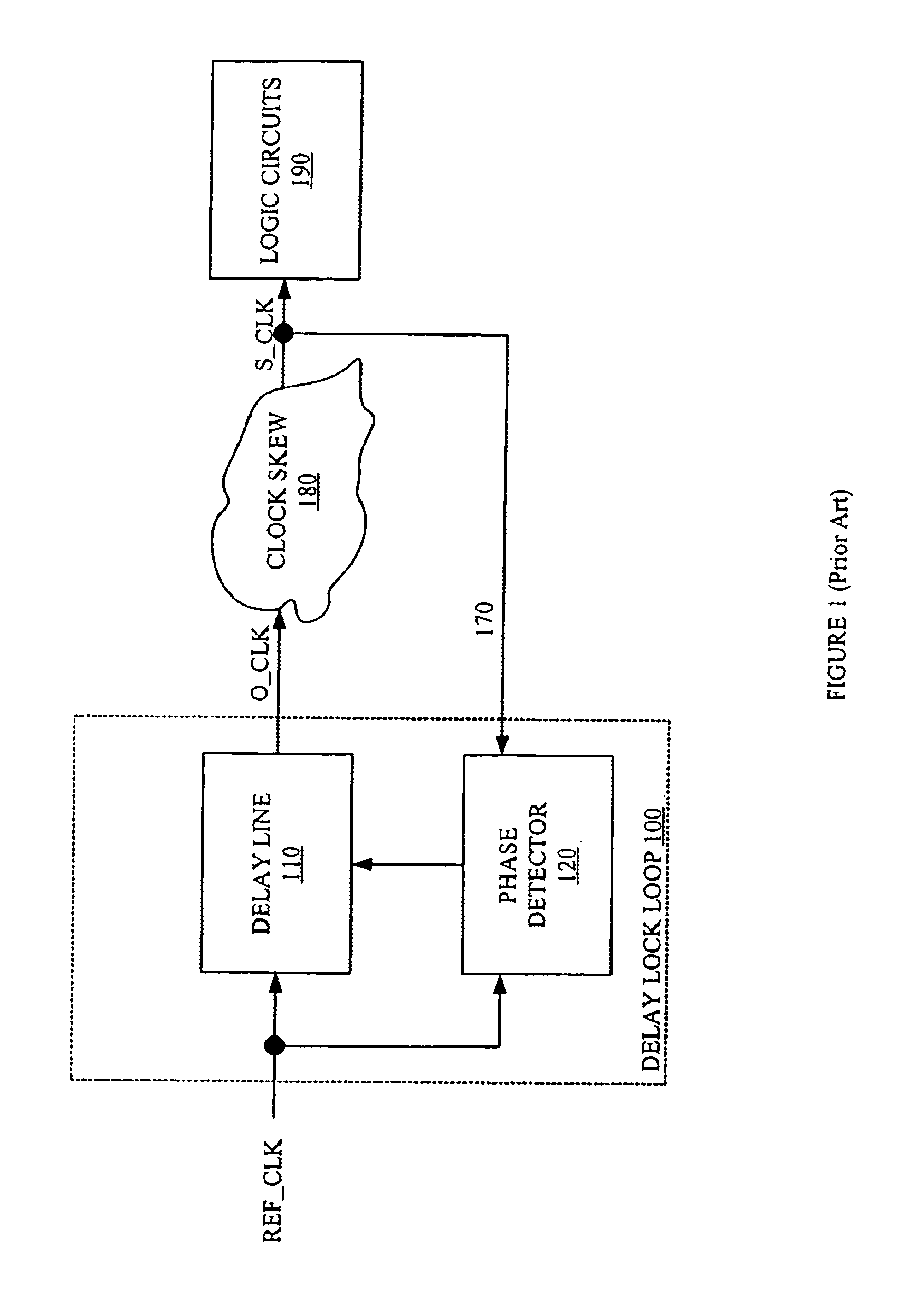
However, due to various problems such as clock buffer delays, high capacitance of heavily loaded clock lines, and propagation delays, the edges of a clock signal in different parts of the system may not be synchronized.
Clock skew can cause digital systems to malfunction.
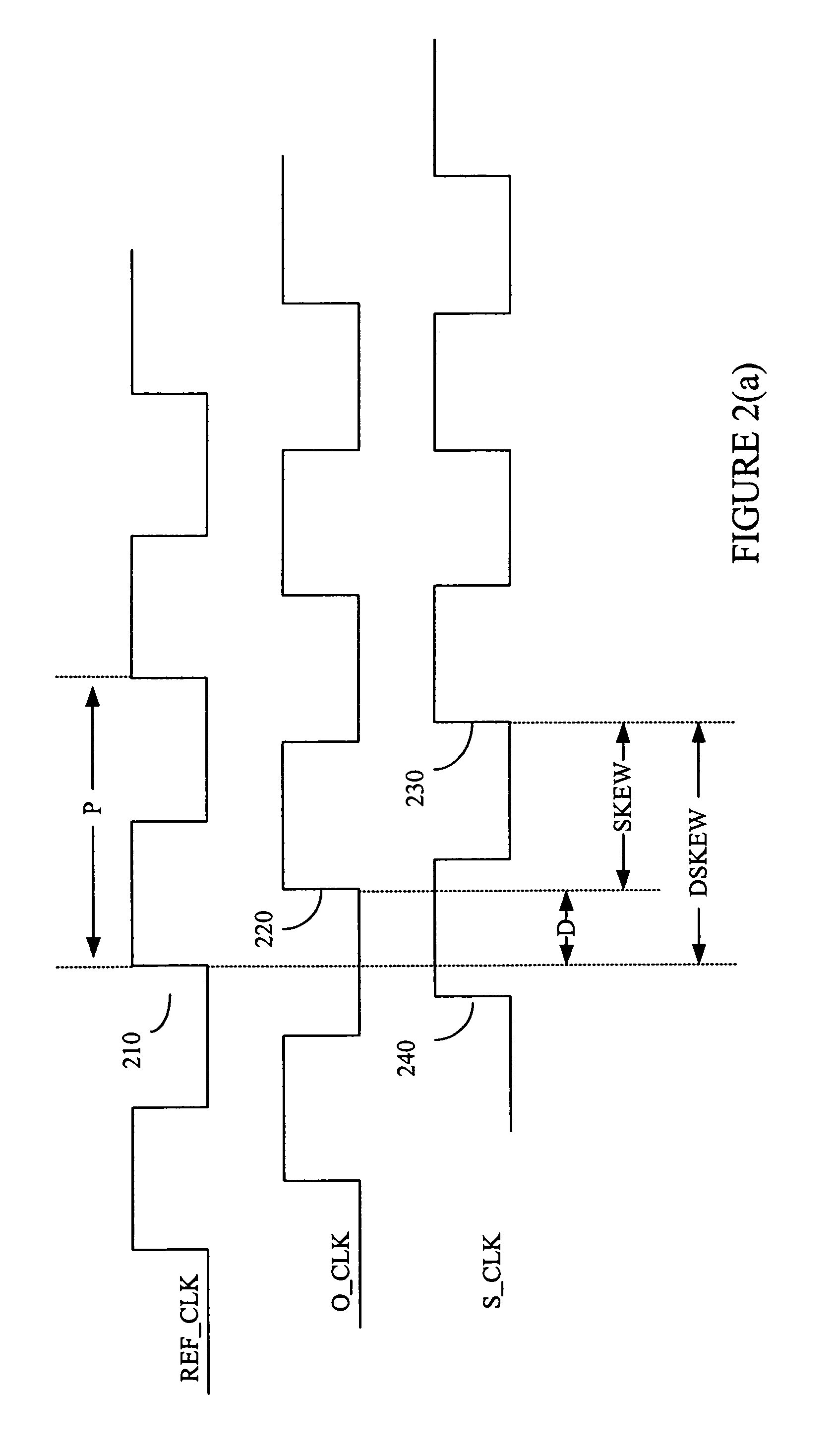
However, if the active edge on the second flip flop is delayed by clock skew, the second flip-flop might not capture the data from the first flip-flop before the first flip-flop changes state.
Although propagation delay DSKEW could be increased to any multiple of period P to achieve synchronization, most delay lock loops do not include a delay line capable of creating such a large propagation delay.
Further complications with clock skew exists in complex digital systems, such as microprocessors and FPGAs, that have multiple clock signals at different frequencies.
However, the clocking circuits add additional skew due to propagation delay and gate switching times. Consequently, frequency adjusted clock signal FREQ_CLK may be skewed compared to both reference clock signal REF_CLK and output clock signal O_CLK.

Method used


Image

  • Synchronized multi-output digital clock manager
  • Synchronized multi-output digital clock manager
  • Synchronized multi-output digital clock manager

Examples


Embodiment Construction

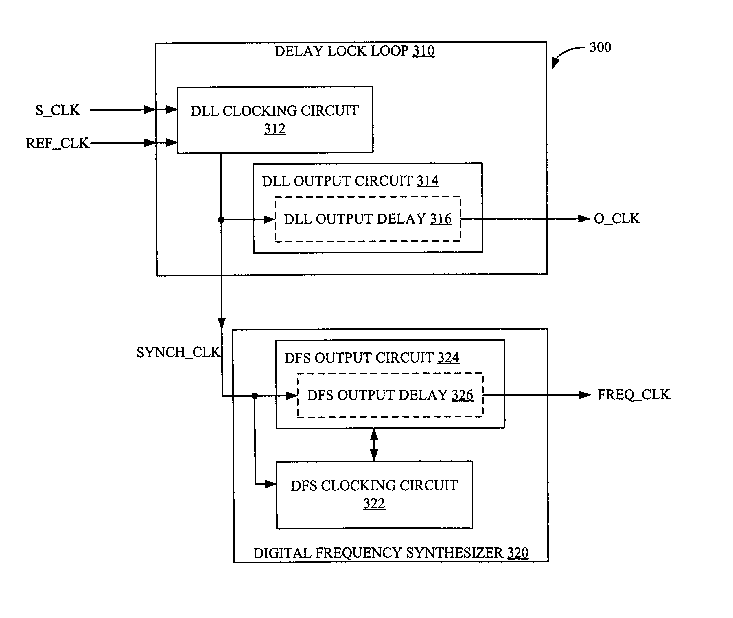
[0039]FIG. 3 is a block diagram of a digital clock manager 300 in accordance with one embodiment of the present invention. Digital clock manager 300, which receives a reference clocks signal REF_CLK and a skewed clock signal S_CLK, generates an output clock signal O_CLK, which causes skewed clock signal S_CLK to be synchronized with reference clock signal REF_CLK, and a frequency adjusted clock signal FREQ_CLK which is phase locked with output clock signal O_CLK during concurrences. Generally, frequency adjusted clock signal FREQ_CLK has an adjusted frequency F_ADJ which is equal to the frequency of output clock signal O_CLK multiplied by a multiplier M and divided by a divider D. If frequency adjusted clock signal FREQ_CLK is in phase with clock signal O_CLK, every Mth rising edge of frequency adjusted clock signal FREQ_CLK aligns with a rising edge of output clock signal O_CLK. The alignments are commonly referred to as concurrences. Reference clock signal REF_CLK and output clock...


PUM


Abstract

A digital clock manager is provided. The digital clock manager generates an output clock signal that causes a skewed clock signal to be synchronized with a reference clock signal. Furthermore, the digital clock manager generates a frequency adjusted clock signal that is synchronized with the output clock signal during concurrence periods. The digital clock manager includes a delay lock loop and a digital frequency synthesizer. The delay lock loop generates a synchronizing clock signal that is provided to the digital frequency synthesizer. The output clock signal lags the synchronizing clock signal by a DLL output delay. Similarly, the frequency adjusted clock signal lags the synchronizing clock signal by a DFS output delay. By matching the DLL output delay to the DFS output delay, the digital clock manager synchronizes the output clock signal and the frequency adjusted clock signal.

Description

FIELD OF THE INVENTION[0001]The present invention relates to digital clocking circuits for digital electronics. More specifically, the present invention relates to digital clock managers capable of generating multiple phase-locked output clock signals of different frequencies.BACKGROUND OF THE INVENTION[0002]Synchronous digital systems, including board level systems and chip level systems, rely on one or more clock signals to synchronize elements across the system. Typically, one or more clock signals are distributed across the system on one or more clock lines. However, due to various problems such as clock buffer delays, high capacitance of heavily loaded clock lines, and propagation delays, the edges of a clock signal in different parts of the system may not be synchronized. The time difference between a rising (or falling) edge in one part of the system with the corresponding rising (or falling) edge in another part of the system is referred to as “clock skew”.[0003]Clock skew c...

Claims


Application Information

Patent Timeline
IPC IPC(8): H03D3/24G06F1/06G06F1/10H03L7/07H03L7/081H04L7/00
CPCG06F1/10H03L7/0814H03L7/07H03L7/0816H03L7/0818
Inventor LOGUE, JOHN D.PERCEY, ANDREW K.GOETTING, F. ERICH
Owner XILINX INC
Learn More