Method and apparatus compensating for frequency drift in a delay locked loop

a delay and loop technology, applied in the field of synchronization of signals, can solve problems such as the inability of the dll to accommodate the delay, the delay occurring, and the decrease in the clock frequency (or the increase of the clock period)

Inactive Publication Date: 2006-05-16
POLARIS INNOVATIONS LTD
View PDF13 Cites 86 Cited by
  • Summary
  • Abstract
  • Description
  • Claims
  • Application Information

AI Technical Summary

Problems solved by technology

Typically, a timing delay occurs when a clock provided externally is used within the apparatus.
A further decrease in the clock frequency (or increase in the clock period) will require a delay which the DLL cannot accommodate (e.g., the delay required will be beyond the maximum delay of the DLL).
A further increase in clock frequency (or decrease in clock period) will require a negative delay which is not possible.
However, the proposed solutions suffer from several disadvantages.
In particular, the use of additional delay or delay lines reduces the area on integrated circuits or chips, and increases jitter, power or current consumption and complexity of the circuit.

Method used


Image

  • Method and apparatus compensating for frequency drift in a delay locked loop
  • Method and apparatus compensating for frequency drift in a delay locked loop
  • Method and apparatus compensating for frequency drift in a delay locked loop

Examples


Embodiment Construction

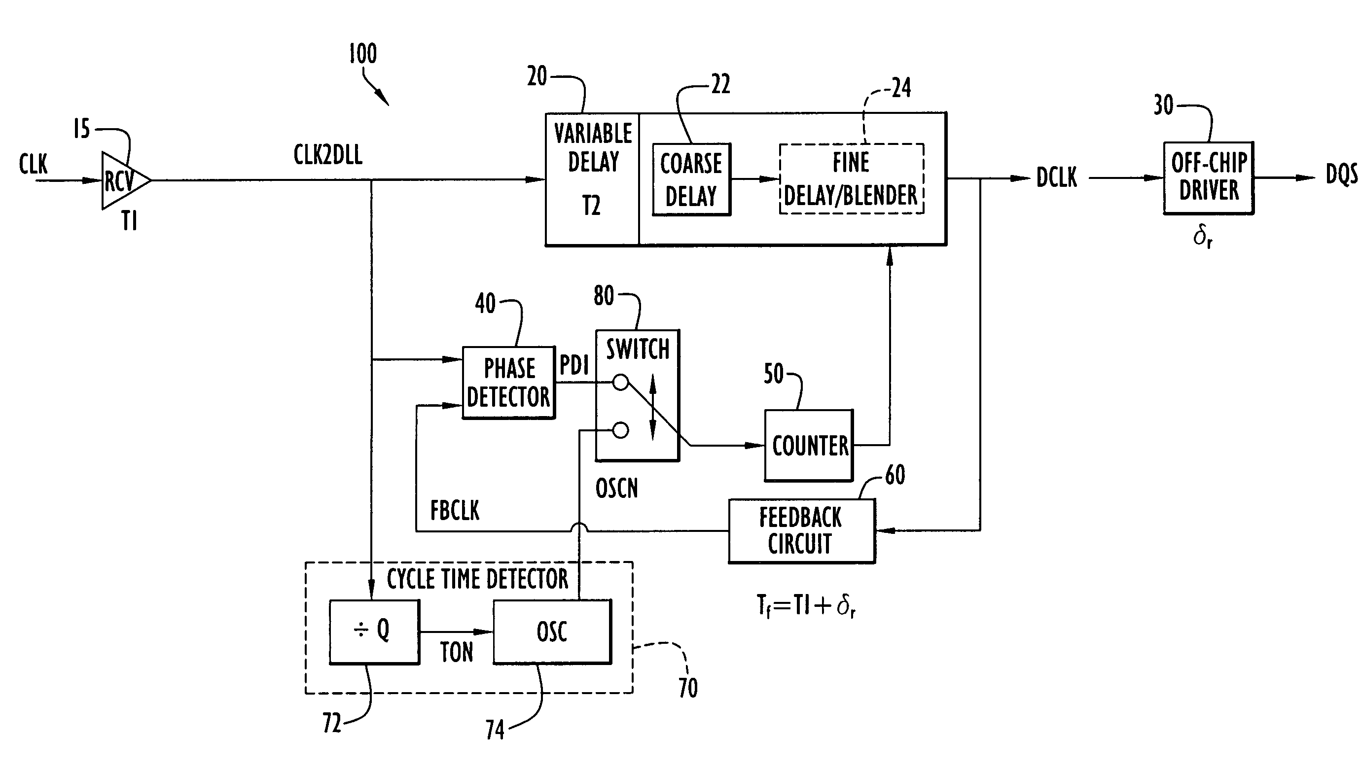
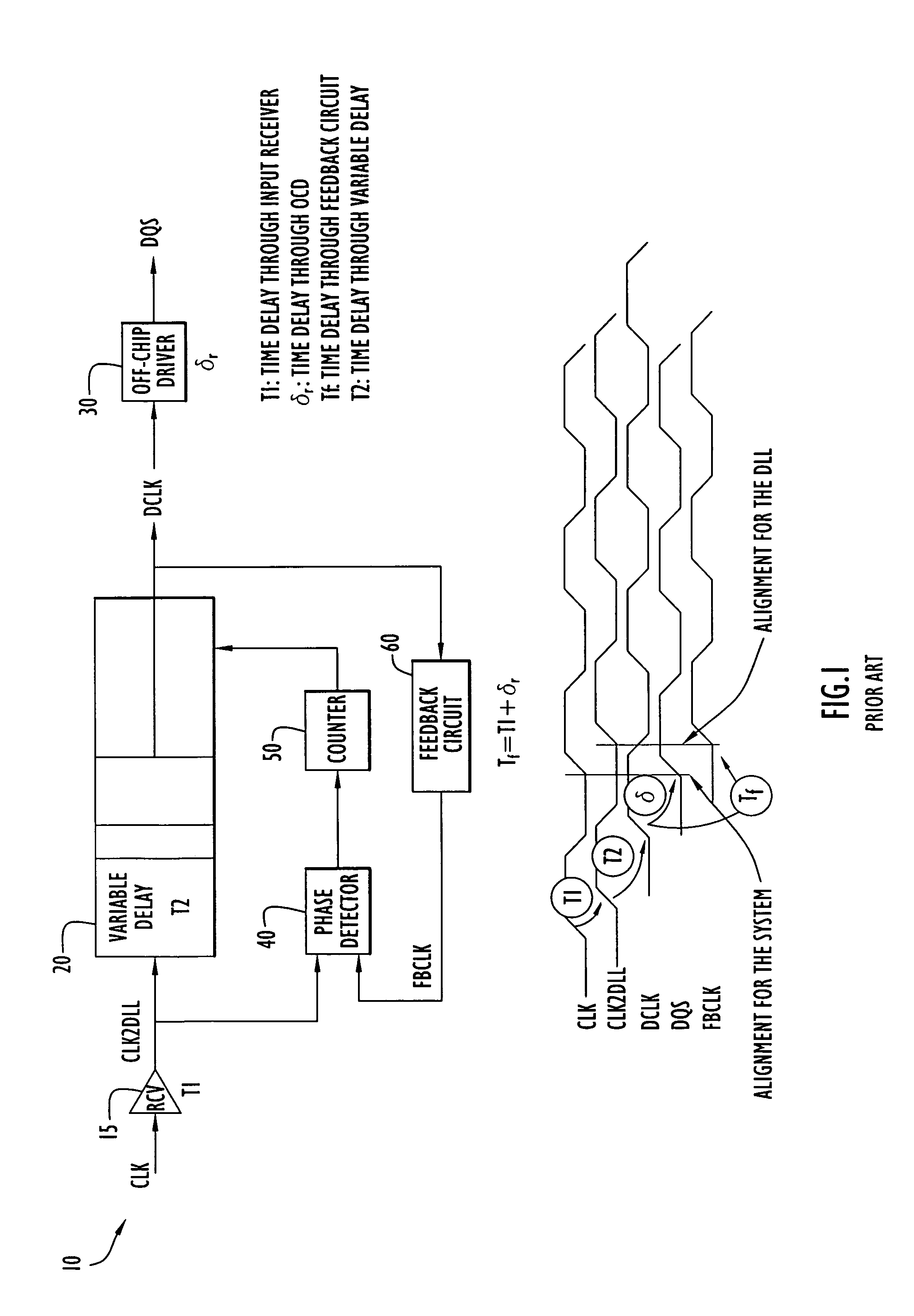
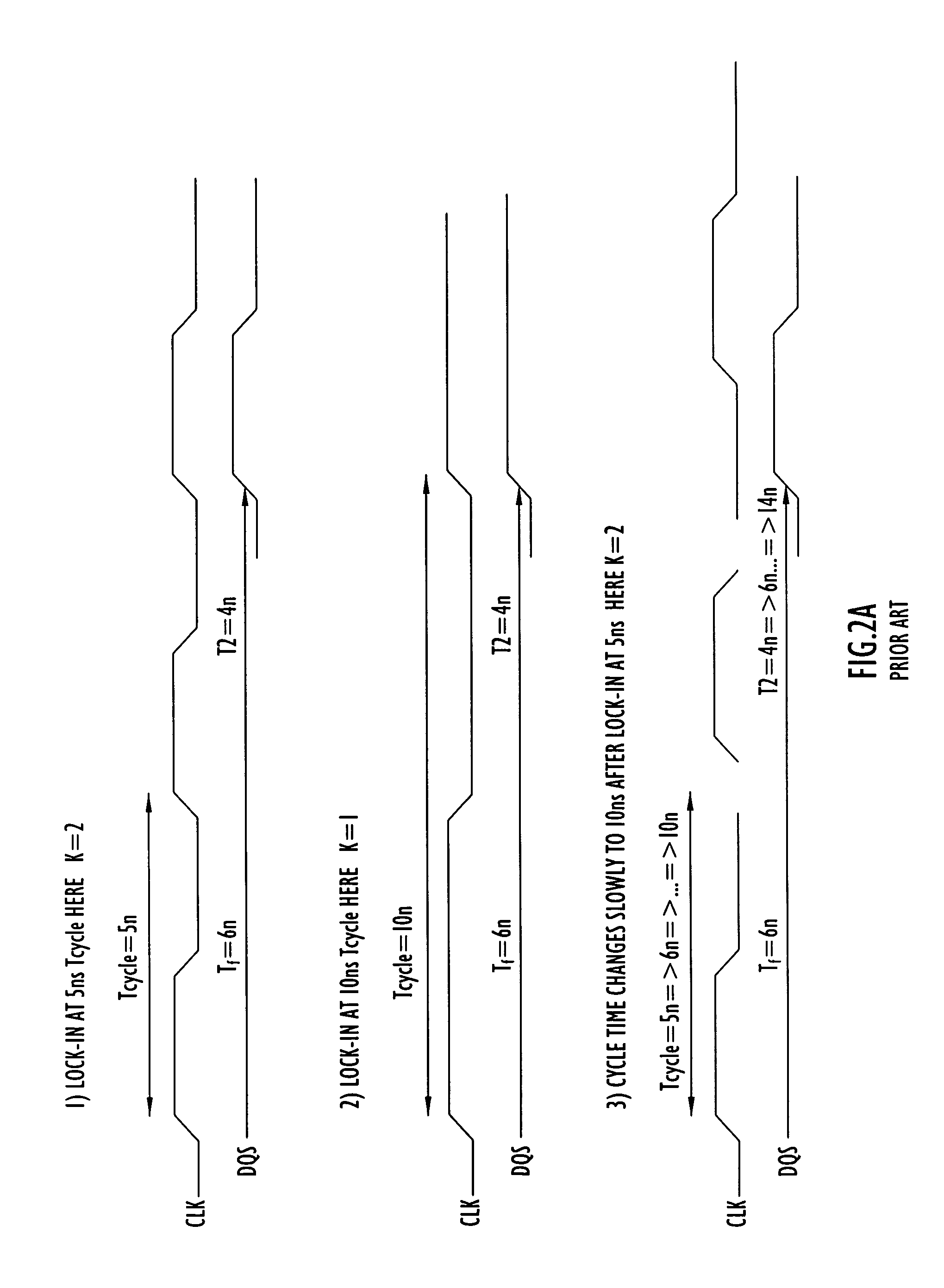
[0022]A delay locked loop circuit (DLL) reduces or compensates for a skew between a clock signal and data or between an external clock and an internal clock as described above. However, these types of circuits may encounter overflow or underflow conditions during periods of clock frequency drift that require delays beyond the capability of the DLL, thereby preventing synchronization of the signals as described above. Accordingly, the present invention DLL accommodates overflow and overflow conditions without the adverse effects of adding additional delay or delay elements or resetting the DLL for operation. A DLL according to the present invention is illustrated in FIGS. 3–4. The DLL typically operates over a clock frequency range to lock onto a particular clock or operational frequency as described below. By way of example only, the DLL may operate in the frequency range of 80 MHz–600 MHz (or clock cycles (Tcycle) in the range of approximately 1.6 to 12.5 nanoseconds); however, the...


PUM


Abstract

A delay locked loop (DLL) according to the present invention includes a cycle time detector to determine the quantity of delay elements within a clock cycle and adjust a DLL counter controlling a DLL variable delay line to enable operation or locking in response to DLL overflow and underflow conditions. The cycle time detector includes a ring oscillator having a strong correlation between the oscillator period and the DLL delay elements. The output of the oscillator controls the counter to provide a new locking position for the DLL in the presence of overflow or underflow conditions. The oscillator is driven for an interval corresponding to the product of the external clock period and the quantity of delay elements in the ring oscillator. In effect, the delay of the DLL is adjusted to the preceding or succeeding external clock period to enable locking in response to overflow or underflow conditions.

Description

BACKGROUND OF THE INVENTION[0001]1. Technical Field[0002]The present invention pertains to synchronization of signals. In particular, the present invention pertains to a delay locked loop circuit that produces a signal synchronized to an externally supplied signal and compensates for frequency drift in that external signal.[0003]2. Discussion of the Related Art[0004]Generally, a delay locked loop circuit (DLL) reduces or compensates for a skew between a clock signal and data or between an external clock and an internal clock. For example, the delay locked loop may be used to synchronize an internal clock of a synchronous memory to an external clock without incurring any error. Typically, a timing delay occurs when a clock provided externally is used within the apparatus. The delay locked loop controls the timing delay to synchronize the internal clock to the external clock.[0005]A conventional DLL is illustrated in FIG. 1. Specifically, DLL 10 includes an input receiver 15, a variab...

Claims


Application Information

Patent Timeline
Patent Type & Authority Patents(United States)
IPC IPC(8): H03L7/18
CPCH03L7/0814H03L7/0818H03L7/10H03L7/0816
Inventor MINZONI, ALESSANDROKIM, JUNG PILL
Owner POLARIS INNOVATIONS LTD
Why Eureka
Try Eureka