Capture clock generator using master and slave delay locked loops

a clock and slave technology, applied in the field of data communication, can solve the problems of clock and data signals not being accurately aligned for some devices, and the accuracy of tuning the delay elements may not be satisfactory,

Inactive Publication Date: 2005-01-04
ROUND ROCK RES LLC
View PDF23 Cites 75 Cited by
  • Summary
  • Abstract
  • Description
  • Claims
  • Application Information

AI Technical Summary

Problems solved by technology

In some cases, tuning the delay elements may not provide satisfactory level of accuracy.
Thus, the clock and data signals may not accurately be aligned for some devices, especially for high speed devices such as new generations of memory devices.

Method used


Image

  • Capture clock generator using master and slave delay locked loops
  • Capture clock generator using master and slave delay locked loops
  • Capture clock generator using master and slave delay locked loops

Examples


Embodiment Construction

The following detailed description refers to the accompanying drawings which form a part hereof, and in which is shown, by way of illustration specific embodiments in which the invention may be practiced. These embodiments are described in sufficient detail to enable those skilled in the art to practice the invention, and it is to be understood that other embodiments may be utilized and that logical, mechanical and electrical changes may be made without departing from the spirit and scope of the resent invention. The following detailed description is, therefore, not to be taken in a limiting sense, and the scope of the invention is defined only by the appended claims.

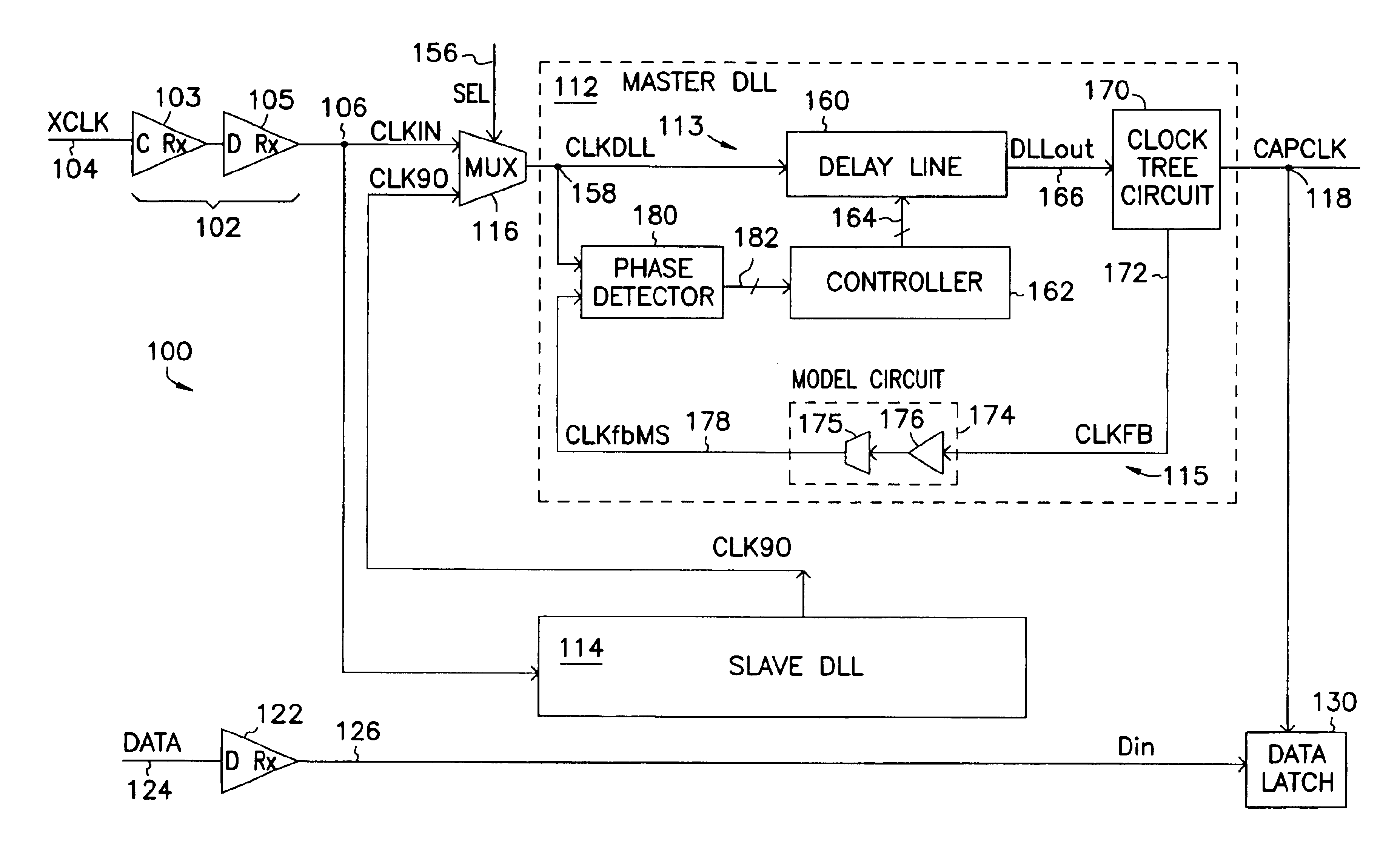
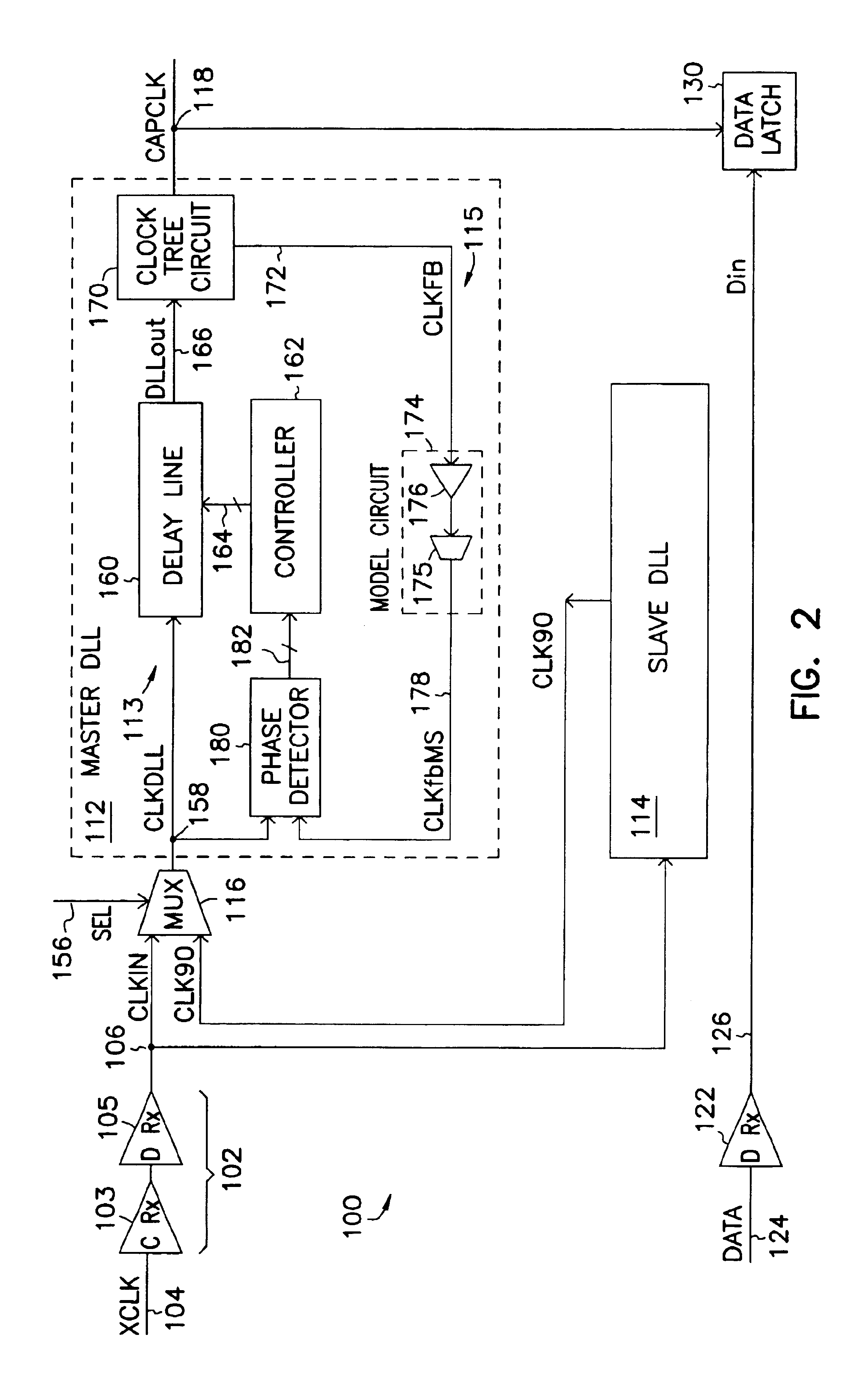
FIG. 2 is a block diagram of a clock generator 100 according to one embodiment of the invention. Clock generator 100 includes a receiving circuit 102, which has a clock receiver 103 (C Rx) connected to a data receiver model 105. Receiving circuit 102 receives an external clock signal XCLK at node 104 and provides an int...


PUM


Abstract

A clock generator comprising a master delay locked loop (DLL) and a slave DLL to capture a data signal. The slave DLL generates a slave output signal based on a clock signal. The master DLL receives the slave output signal and compensates variations in delays of the data and clock signals to generate a capture clock signal. When the master and slave DLLs are locked, the capture clock signal is center aligned with the data signal.

Description

TECHNICAL FIELD OF THE INVENTIONThe present invention relates generally to data communication, and in particular to a capture clock generator.BACKGROUND OF THE INVENTIONIn data communication, data are often transferred from one circuit to another circuit for processing. To capture a data signal, a data capture circuit is used. The data capture circuit normally uses a clock signal to capture the data signal. The clock signal can be a system clock signal or an internal clock signal generated by a clock generator.FIG. 1A is a block diagram illustrating one traditional clock and data signal relationship of a capture circuit. In this method, the system clock signal is edge aligned with the captured data signal while the capture clock signal is center aligned with the data eye. In other terms, the capture clock signal is 90 degrees out of phase or one-fourth clock cycle delayed from the system clock signal and is center aligned with the data signal.FIG. 1B illustrates possible data and cl...

Claims


Application Information

Patent Timeline
Patent Type & Authority Patents(United States)
IPC IPC(8): G11C7/00G11C7/10G11C7/22H03L7/081H03L7/07H03L7/08H04L7/02
CPCG11C7/1078G11C7/1087G11C7/22H03L7/07H03L7/0812G11C7/222H04L7/02H03L7/0814H03L7/0816
Inventor LIN, FENG
Owner ROUND ROCK RES LLC
Why Eureka
Try Eureka