Duty cycle correction circuits suitable for use in delay-locked loops and methods of correcting duty cycles of periodic signals

a duty cycle correction and delay-locked loop technology, applied in pulse manipulation, pulse technique, instruments, etc., can solve the problems of limiting the reliability of data capture, and the use of analog duty cycle correction circuits may operate to limit the performance characteristics of clock signal generators

Inactive Publication Date: 2007-04-03
SAMSUNG ELECTRONICS CO LTD
View PDF11 Cites 78 Cited by
  • Summary
  • Abstract
  • Description
  • Claims
  • Application Information

AI Technical Summary

Problems solved by technology

However, in the second scenario, when the external clock ECLK is used to synchronize data capture at a dual data rate (DDR), then the non-uniform duty cycle associated with the external clock ECLK will typically operate to limit the reliability of data capture.
Unfortunately, the use of an analog duty cycle correction circuit may operate to limit the performance characteristics of the clock signal generator 200 upon start-up (i.e., power up) because of inherent start-up delays (e.g., capacitor charging delays).

Method used


Image

  • Duty cycle correction circuits suitable for use in delay-locked loops and methods of correcting duty cycles of periodic signals
  • Duty cycle correction circuits suitable for use in delay-locked loops and methods of correcting duty cycles of periodic signals
  • Duty cycle correction circuits suitable for use in delay-locked loops and methods of correcting duty cycles of periodic signals

Examples


Embodiment Construction

[0020]The present invention now will be described more fully herein with reference to the accompanying drawings, in which preferred embodiments of the invention are shown. This invention may, however, be embodied in many different forms and should not be construed as being limited to the embodiments set forth herein; rather, these embodiments are provided so that this disclosure will be thorough and complete, and will fully convey the scope of the invention to those skilled in the art. Like reference numerals refer to like elements throughout. Signals may also be synchronized and / or undergo minor boolean operations (e.g., inversion) without being considered different signals. The suffix B (or prefix symbol “ / ”) to a signal name may also denote a complementary data or information signal or an active low control signal, for example.

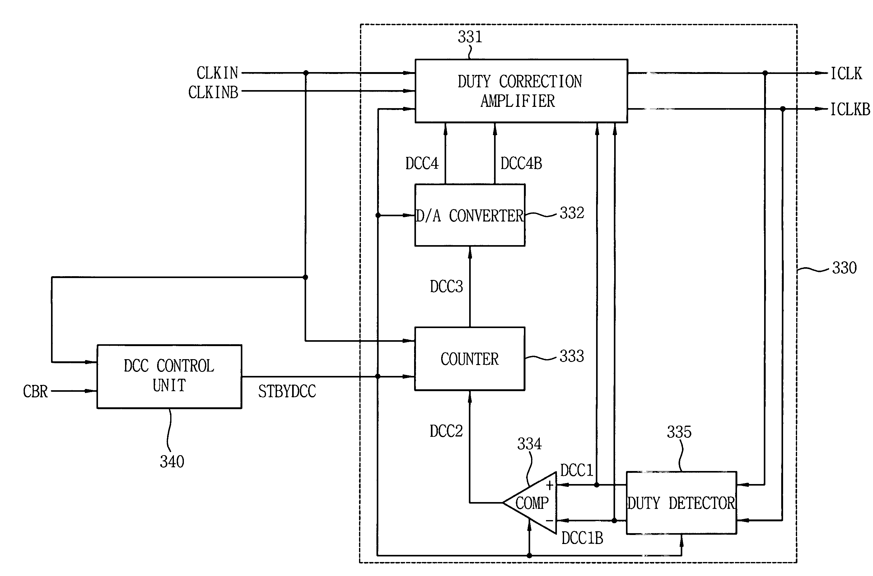
[0021]Referring now to FIG. 3, a duty cycle correction circuit 330 according to an embodiment of the invention includes a duty cycle correction amplifier 3...


PUM


Abstract

Delay-locked loop integrated circuits include a duty cycle correction circuit. This duty cycle correction circuit generates at least one output clock signal having a substantially uniform duty cycle in response to at least one input clock signal having a non-uniform duty cycle. The duty cycle correction circuit is also responsive to a standby control signal that synchronizes timing of power-saving duty cycle update operations within the duty cycle correction circuit. These update operations reset the set point of the correction circuit.

Description

REFERENCE TO PRIORITY APPLICATION[0001]This application claims priority to Korean Application Serial No. 2003-88986, filed Dec. 9, 2003, the disclosure of which is hereby incorporated herein by reference.FIELD OF THE INVENTION[0002]The present invention relates to integrated circuit devices and, more particularly, to integrated circuit devices that synchronize timing of clock and data signals.BACKGROUND OF THE INVENTION[0003]Achieving a high degree of synchronization between data signals and clocks can be a significant aspect to the reliable transmission of data between integrated circuit devices, such as integrated circuit memory devices (e.g., DRAM devices) and memory controllers that transmit data to and from the integrated circuit memory devices. To achieve such high levels of synchronization between data signals and clocks, phase-locked loop (PLL) integrated circuits and delay-locked loop (DLL) integrated circuits have been developed to synchronize the timing of internal clocks...

Claims


Application Information

Patent Timeline
Patent Type & Authority Patents(United States)
IPC IPC(8): H03K3/017G11C8/00H03K5/04H03K5/135H03K5/151H03K5/156H03L7/081
CPCH03K5/135H03K5/151H03K5/1565H03L7/0812G11C8/00
Inventor CHO, GEUN-HEEKIM, KYU-HYOUN
Owner SAMSUNG ELECTRONICS CO LTD
Why Eureka
Try Eureka