Current sensor and power conversion apparatus including the same
a technology of current sensor and power conversion apparatus, which is applied in the direction of voltage/current isolation, dc-ac conversion without reversal, instruments, etc., can solve the problems of increasing the rising time of an output of the current sensor and the measurement error of the current sensor, so as to reduce the height
- Summary
- Abstract
- Description
- Claims
- Application Information
AI Technical Summary
Benefits of technology
Problems solved by technology
Method used
Image
Examples
first preferred embodiment
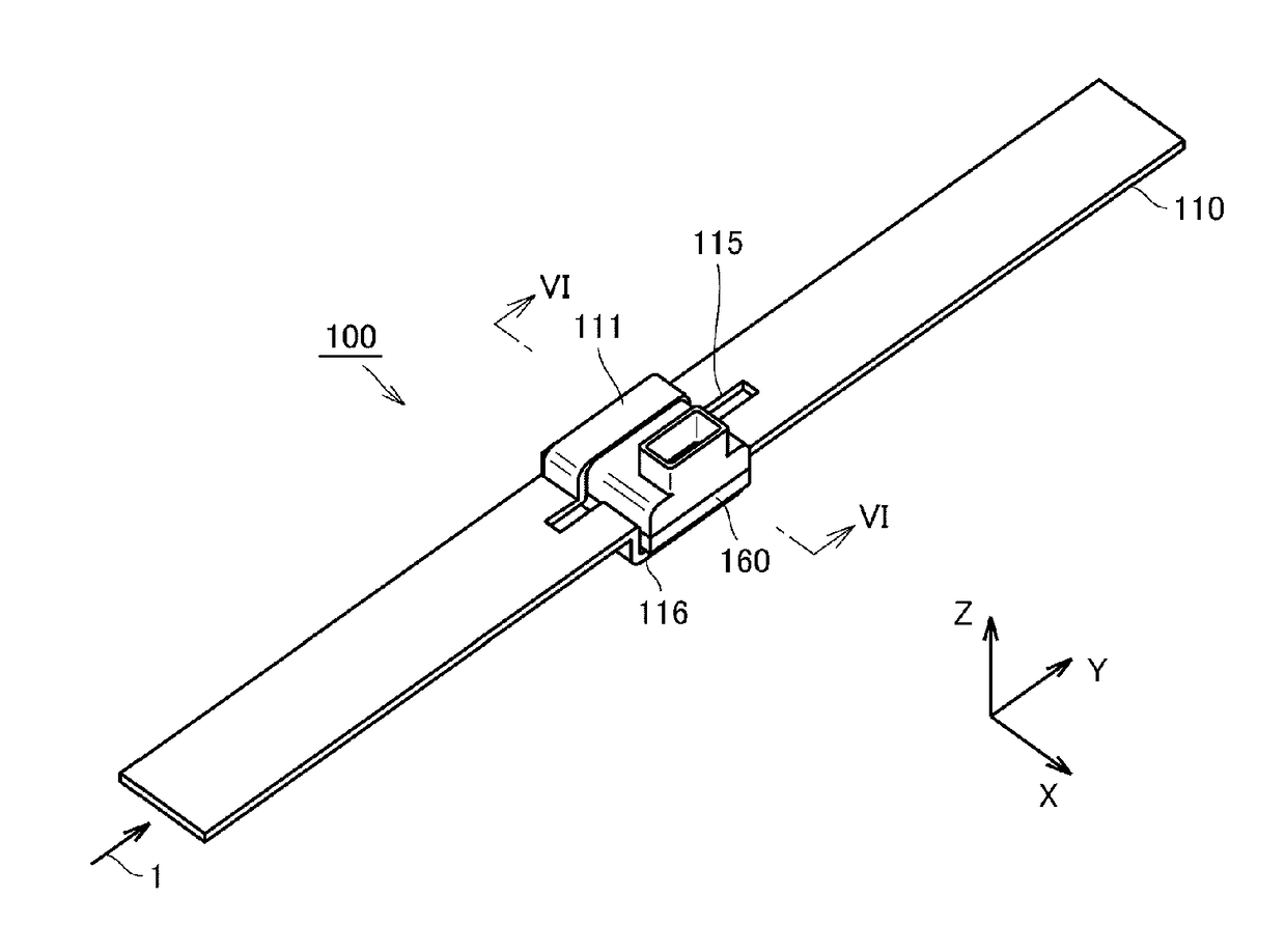
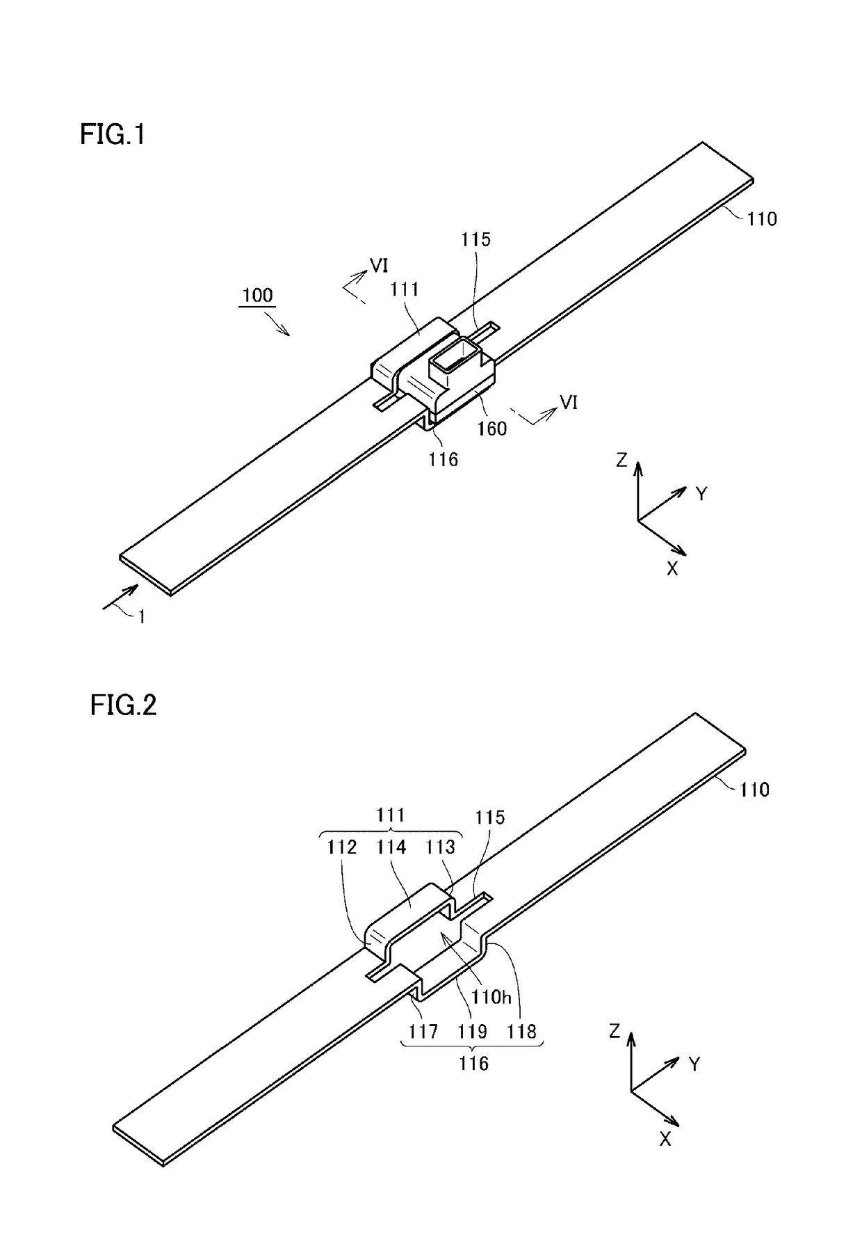
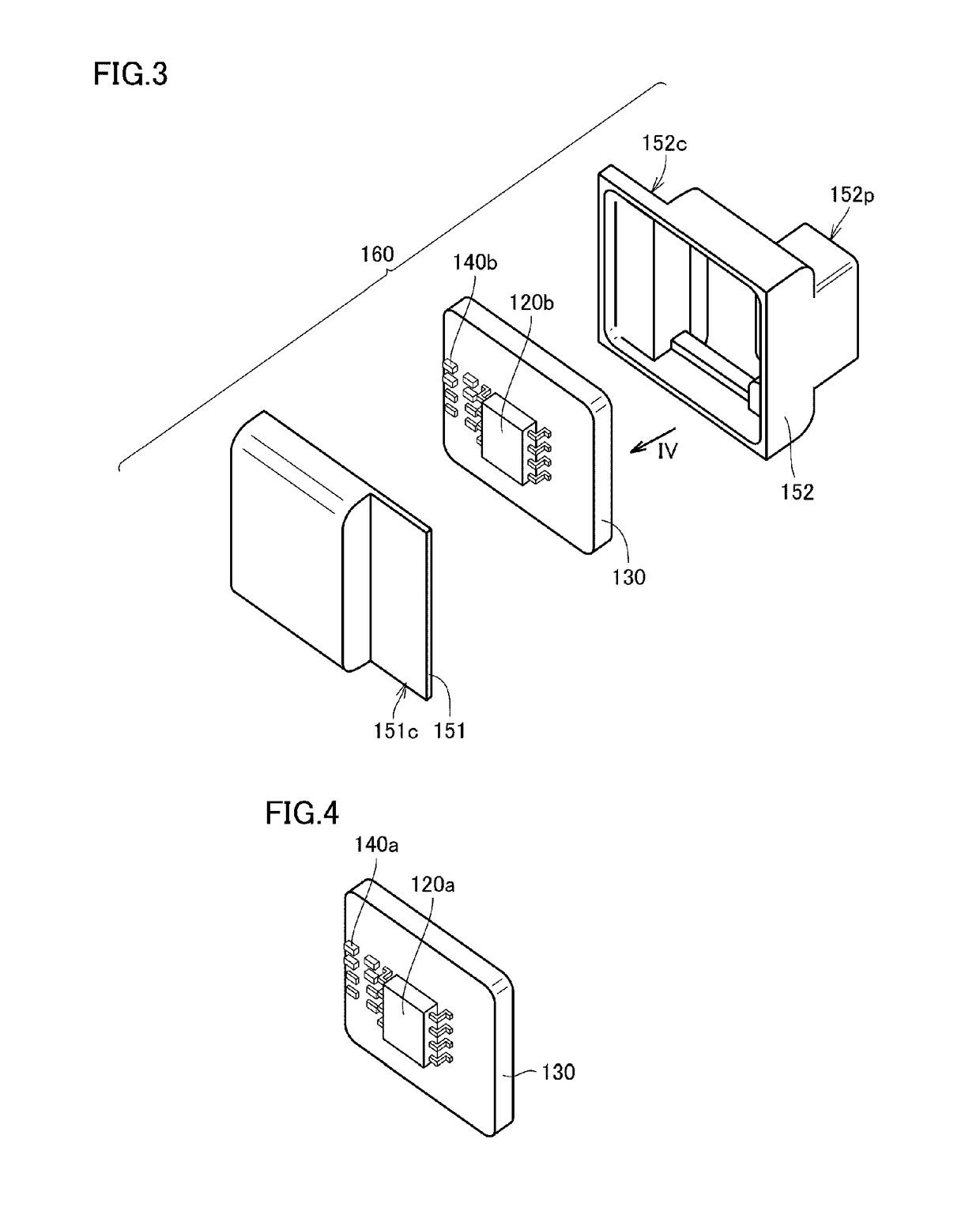
[0056]FIG. 1 is a perspective view illustrating an outer appearance of a current sensor according to a first preferred embodiment of the present invention. FIG. 2 is a perspective view illustrating an outer appearance of a primary conductor included in the current sensor in the first preferred embodiment of the present invention. FIG. 3 is an exploded perspective view illustrating the configuration of a magnetic sensor unit included in the current sensor in the first preferred embodiment of the present invention. FIG. 4 is a perspective view when a substrate of the magnetic sensor unit included in the current sensor in the first preferred embodiment of the present invention is viewed from an IV direction in FIG. 3. FIG. 5 is a perspective view illustrating an outer appearance of a housing of the magnetic sensor unit included in the current sensor in the first preferred embodiment of the present invention. FIG. 6 is a cross-sectional view of the current sensor in the first preferred ...
second preferred embodiment
[0131]Hereinafter, a current sensor according to a second preferred embodiment of the present invention will be described. The current sensor in the present preferred embodiment is different from the current sensor 100 in the first preferred embodiment only in that each of the first magnetic sensor 120a and the second magnetic sensor 120b includes a magnetoresistive element, instead of the Hall element. Therefore, description of the same structure and configurations as those of the current sensor 100 in the first preferred embodiment is not repeated.
[0132]FIG. 17 is a cross-sectional view schematically illustrating magnetic fields generated by flow of a current as a measurement target in the current sensor in the second preferred embodiment of the present invention. FIG. 18 is a circuit diagram illustrating the circuit configuration of the current sensor in the second preferred embodiment of the present invention. FIG. 17 does not illustrate the housing 150. FIG. 17 is a cross-secti...
third preferred embodiment
[0142]Hereinafter, a current sensor according to a third preferred embodiment of the present invention will be described with reference to the drawings. The current sensor in the present preferred embodiment is different from the current sensor 100 in the first preferred embodiment primarily in that all of the first magnetic sensor 120a, the second magnetic sensor 120b, the plurality of electronic components 140a, and the plurality of electronic components 140b are mounted on one main surface of the substrate 130. Therefore, description of the same configurations as those of the current sensor 100 in the first preferred embodiment is not repeated.
[0143]FIG. 19 is a cross-sectional view of the current sensor in the third preferred embodiment of the present invention. FIG. 19 is a cross-sectional view similar to FIG. 6. As illustrated in FIG. 19, in a current sensor 300 in the third preferred embodiment of the present invention, the first magnetic sensor 120a and the second magnetic s...
PUM
 Abstract
Description
Claims
Application Information
 - R&D
- Intellectual Property
- Life Sciences
- Materials
- Tech Scout
- Unparalleled Data Quality
- Higher Quality Content
- 60% Fewer Hallucinations
Browse by: Latest US Patents, China's latest patents, Technical Efficacy Thesaurus, Application Domain, Technology Topic, Popular Technical Reports.
© 2025 PatSnap. All rights reserved.Legal|Privacy policy|Modern Slavery Act Transparency Statement|Sitemap|About US| Contact US: help@patsnap.com


