Shock Absorption Device for Pneumatic Tool

Inactive Publication Date: 2018-07-19
LIN JHIH JHONG
View PDF4 Cites 3 Cited by
  • Summary
  • Abstract
  • Description
  • Claims
  • Application Information

AI Technical Summary

Benefits of technology

[0007]The primary objective of the present invention is to provide a shock absorption device for a pneumatic tool in which plural buffer springs are accommodated in a chamber of a fitting sleeve, and the plural buffer springs extend out of multiple positioning sleeves respectively so that the multiple positioning sleeves separate and fix the plural buffer springs individually to scatter and to buffer reaction force evenly, thus having multiple shock absorption; when the plural buffer springs press the multiple

Problems solved by technology

However, when the piston member 40 slides backward to impact the valve unit 20, a reaction force produces and passes toward the user's hand, thus making gripping the pneumatic tool difficult and hurting the user's waist easily.
But when the pis

Method used


Image

  • Shock Absorption Device for Pneumatic Tool
  • Shock Absorption Device for Pneumatic Tool
  • Shock Absorption Device for Pneumatic Tool

Examples


Example

[0024]The present invention will be clearer from the following description when viewed together with the accompanying drawings, which show, for purpose of illustration only, preferred embodiments in accordance with the present invention.

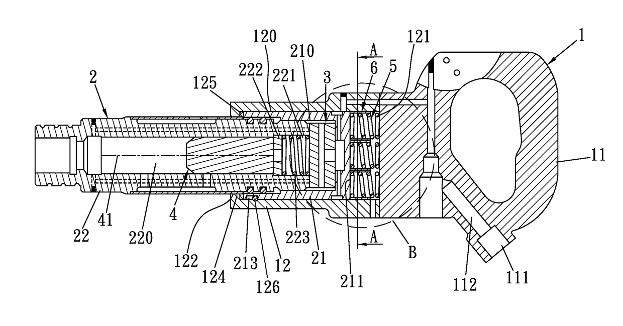
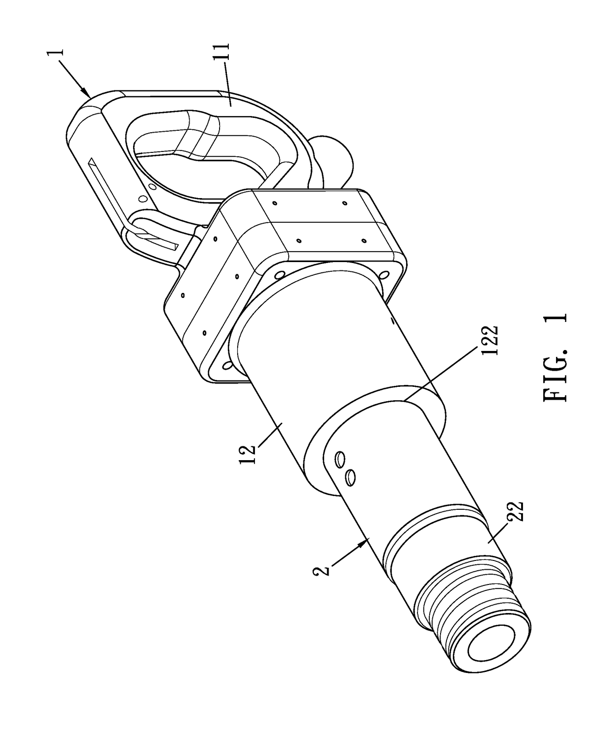
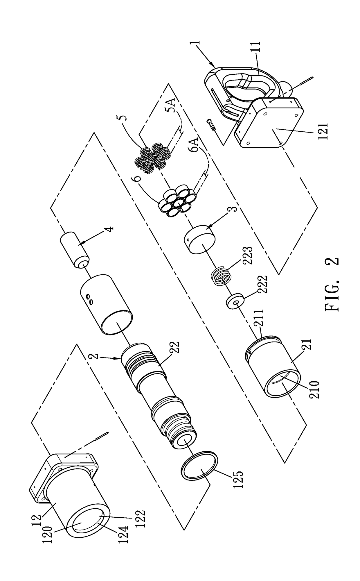
[0025]FIGS. 1 to 5 show a shock absorption device for a pneumatic tool according to a preferred embodiment of the present invention. The pneumatic tool comprises: a body 1, a cylinder 2, a valve unit 3, a piston member 4, plural buffer springs 5, and multiple positioning sleeves 6. The body 1 includes a grip 11 and a fitting sleeve 12 fitted with the grip 11. The grip 11 has an air inlet segment 111, an air passage 112 communicating with the air inlet segment 111, and a control switch (not shown) for controlling air to flow into the air inlet segment 111. The fitting sleeve 12 has a chamber 120 defined therein, a close face 121 formed on a first end thereof, an opening 122 formed on a second end thereof, and a stop rib 124 extending inwardly from a p...


PUM


Abstract

A device absorbs shock in a pneumatic tool containing a body, a cylinder, a valve unit, a piston member, plural buffer springs, and multiple fitting sleeves. The body includes a grip and a fitting sleeve fitted with the grip. The fitting sleeve has a chamber, a close face formed on a first end thereof, and an opening formed on a second end thereof. Each fitting sleeve is hollow and includes a limitation length forming along a hollow extending direction and shorter than a largest length. Multiple positioning sleeves are defined between a close face of the fitting sleeve and an abutting portion of the cylinder, and the multiple positioning sleeves are hollow so as to accommodate plural buffer springs. Because the limitation length is shorter than the largest length, the plural buffer springs extend out of the multiple positioning sleeves respectively.

Description

[0001]This application is a Continuation-in-Part of application Ser. No. 14 / 662,297, filed Mar. 19, 2015.BACKGROUND OF THE INVENTIONField of the Invention[0002]The present invention relates to a shock absorption structure and, more particularly, to a shock absorption device for a pneumatic tool which reduces operating vibration.Description of the Prior Art[0003]A conventional pneumatic tool is driven by high pressure air used as a power source. With reference to FIG. 10, the conventional pneumatic tool contains: a grip 10, a valve unit 20, a cylinder 30, and a piston member 40. The grip 10 includes an air inlet segment 101 connected with high pressure air, an air passage 102 communicating with the air inlet segment 101, a control switch (not shown) for controlling air to flow into the air inlet segment 101, and a cylindrical portion 103. The cylindrical portion 103 has a chamber 104 defined therein and communicating with the air passage 102. The valve unit 20 is mounted in the chamb...

Claims


Application Information

Patent Timeline
IPC IPC(8): B25D17/24B25D9/04
CPCB25D17/24B25D9/04B25D2250/181B25D2250/371B25D2250/285
Inventor LIN, JHIH JHONG
Owner LIN JHIH JHONG
Why Eureka
Try Eureka