Rolling bearing and method for the production thereof

Inactive Publication Date: 2013-06-11
SCHAEFFLER TECH AG & CO KG
View PDF34 Cites 2 Cited by
  • Summary
  • Abstract
  • Description
  • Claims
  • Application Information

AI Technical Summary

Benefits of technology

[0004]The present invention is based on the object of making available a method for producing a roller bearing with which a roller bearing can be made a

Problems solved by technology

However, it is to be noted that the subject matters of all the subclaims do not solve all the inventive problems to the same degree.
Furthermore, it is to b

Method used


Image

  • Rolling bearing and method for the production thereof
  • Rolling bearing and method for the production thereof
  • Rolling bearing and method for the production thereof

Examples


Example

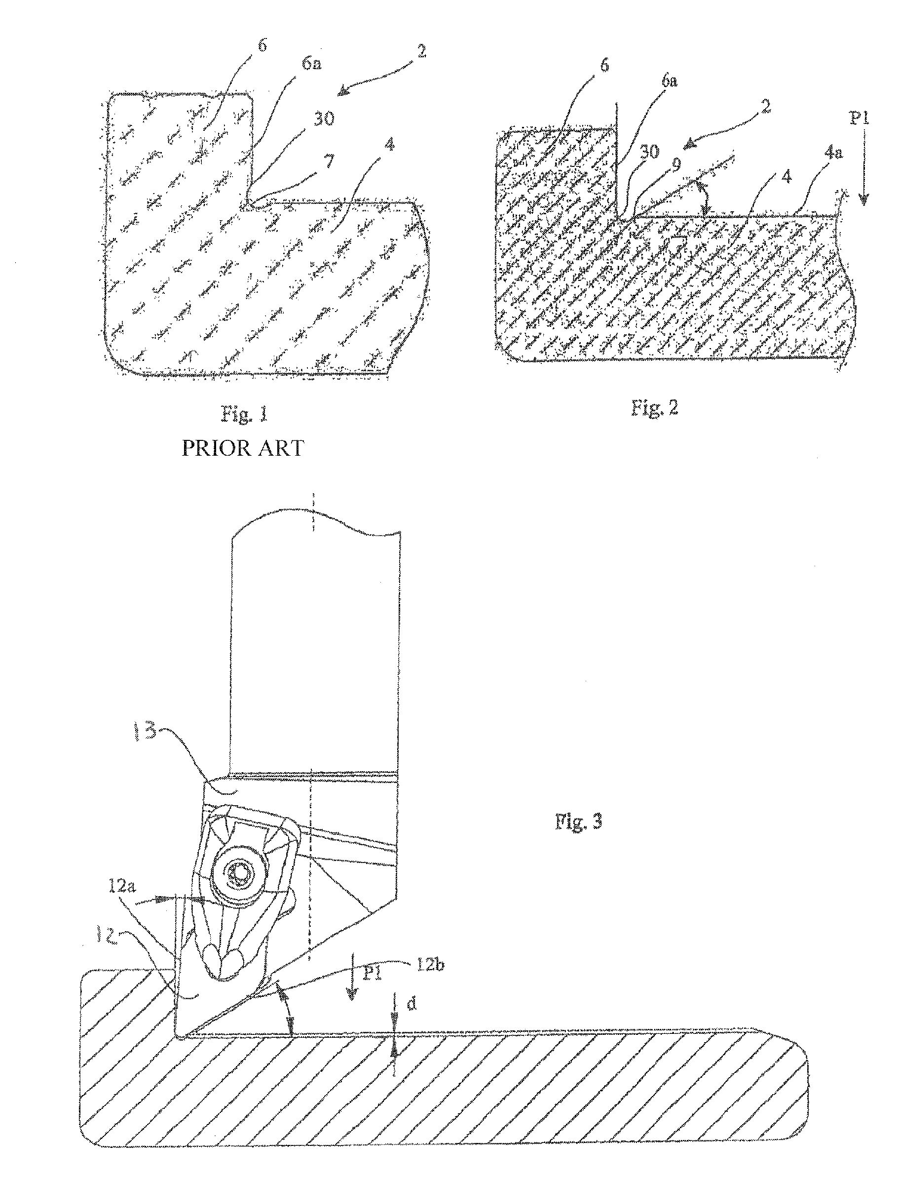
[0043]FIG. 1 shows a detail illustration of a bearing ring 2 manufactured using a method known from the prior art. The reference symbol 4 here refers to a central region of the bearing ring and the reference symbol 6 refers to a lateral rim. The rim running face 6a of the rim is facing a roller body (not shown).

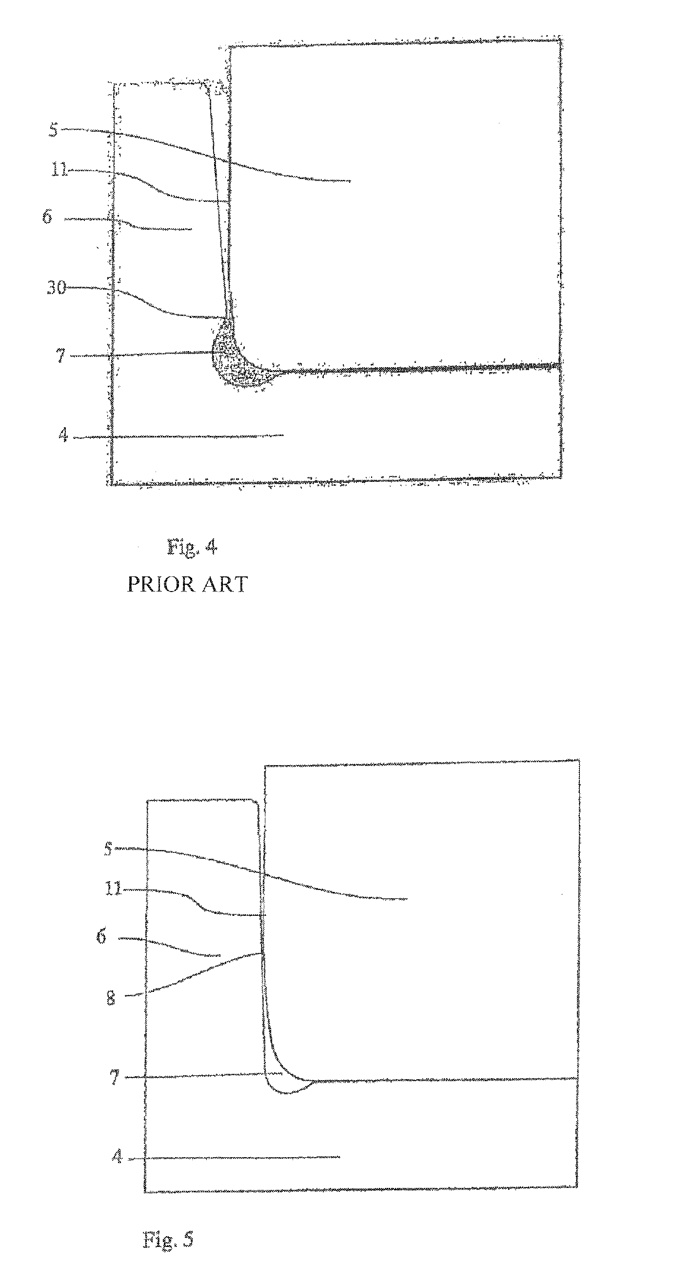
[0044]As mentioned at the beginning, in the method known from the prior art the notch 7 or the grinding undercut is formed in the material before the hardening process. The material is hardened only after this. In this method it is also still necessary to grind the rim running face 6a. Therefore, the notch 7, as shown in FIG. 1, is formed in an oblique direction with respect to the rim 6 and the central region 4. As a result, an edge 30 is produced in the rim running face 6a in the prior art. This sharp edge 30 can have unfavorable effects on the start of axial movement, in particular of planar roller end faces.

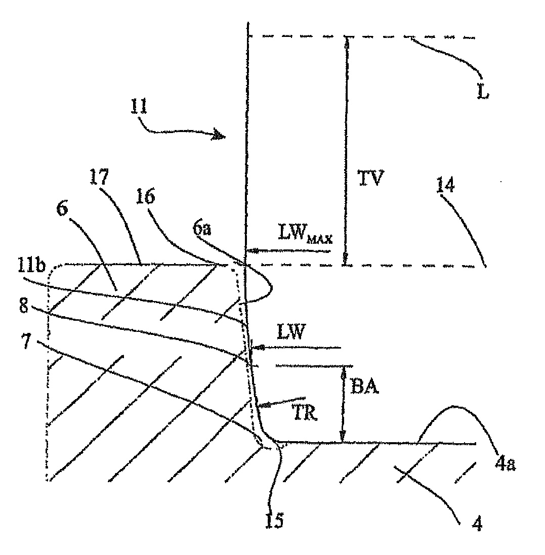
[0045]FIG. 2 shows a bearing ring manufactured according to the i...


PUM

PropertyMeasurementUnit
Angleaaaaaaaaaa
Angleaaaaaaaaaa
Angleaaaaaaaaaa

Abstract

A method for producing a bearing ring for a roiling bearing, the bearing ring comprising a raceway for a rolling member as well as at least one lateral rim for axially guiding the rolling member. In one step of said method, a notch is introduced into a running surface of the bearing ring which faces the rolling member. The final contour of the bearing ring is created by means of a hard turning process.

Description

BACKGROUND OF THE INVENTION[0001]The present invention relates to a roller bearing and a method for the production thereof. In particular, the invention relates to a method for producing a bearing ring of the roller bearing and an associated roller body.[0002]Various roller bearings are known from the prior art. For example, roller bearings are known in which a bearing ring, i.e. the outer ring and / or the inner ring, has a rim in order to absorb axial forces acting on the bearing. In methods for producing roller bearings which are known from the prior art, the respective bearing rings are produced by means of a turning method and subsequently what is referred to as a grinding undercut is provided in a still unhardened state in a corner region between the raceway of the bearing ring and the lateral rim. This grinding undercut is required to be able to subsequently grind the raceway and the rim running face.[0003]This grinding undercut results in a sharp edge in the rim running face. ...

Claims


Application Information

Patent Timeline
IPC IPC(8): F16C33/64F16C33/58F16C33/36
CPCF16C19/225F16C19/26F16C33/34F16C33/585F16C19/22F16C33/64Y10T29/49693F16C2240/40F16C2240/50Y10T29/49679
Inventor WEIDNER, ALEXANDERHENNEFELDER, MARKUSGRAF, PAUL
Owner SCHAEFFLER TECH AG & CO KG
Why Eureka
Try Eureka