Touch sensor unit

Active Publication Date: 2017-11-30
MITSUBA CORP
View PDF6 Cites 3 Cited by
  • Summary
  • Abstract
  • Description
  • Claims
  • Application Information

AI Technical Summary

Benefits of technology

[0014]According to the present invention, the attachment body is provided with a protruding portion which is disposed on one side of the elastic base portion, the gap portion is provided between the protruding portion and the elastic base portion, and the height from the attachment body to the distal end of the protruding portion is smaller than the height from the attachment body to the sensor portion. Therefore, when the sensor portion and the elastic base portion are elastically deformed upon contact of a blockage, the

Problems solved by technology

Accordingly, if, for example, a blockage strikes the holding member, the corner portion may damage the holding member.
Simply increas

Method used


Image

  • Touch sensor unit
  • Touch sensor unit
  • Touch sensor unit

Examples


Example

[0026]Hereinafter, the first embodiment of the present invention will be described in detail with reference to the drawings.

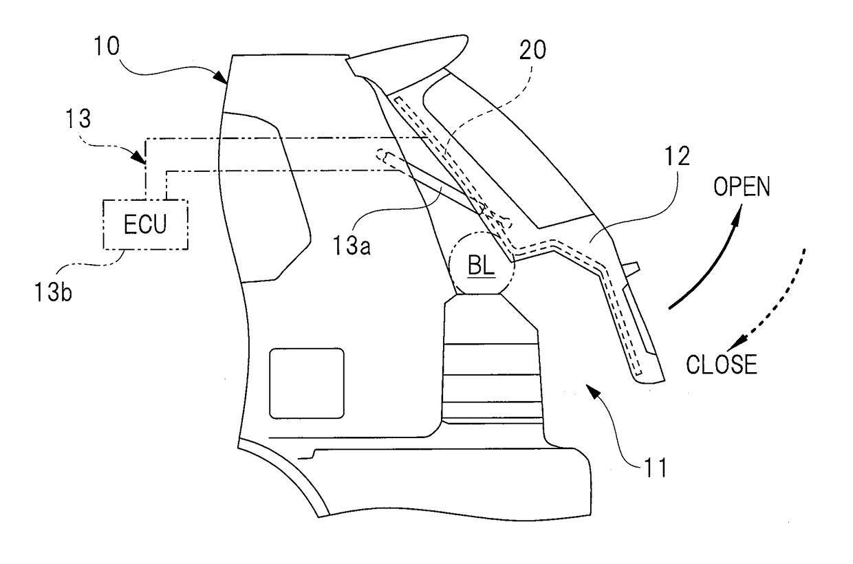
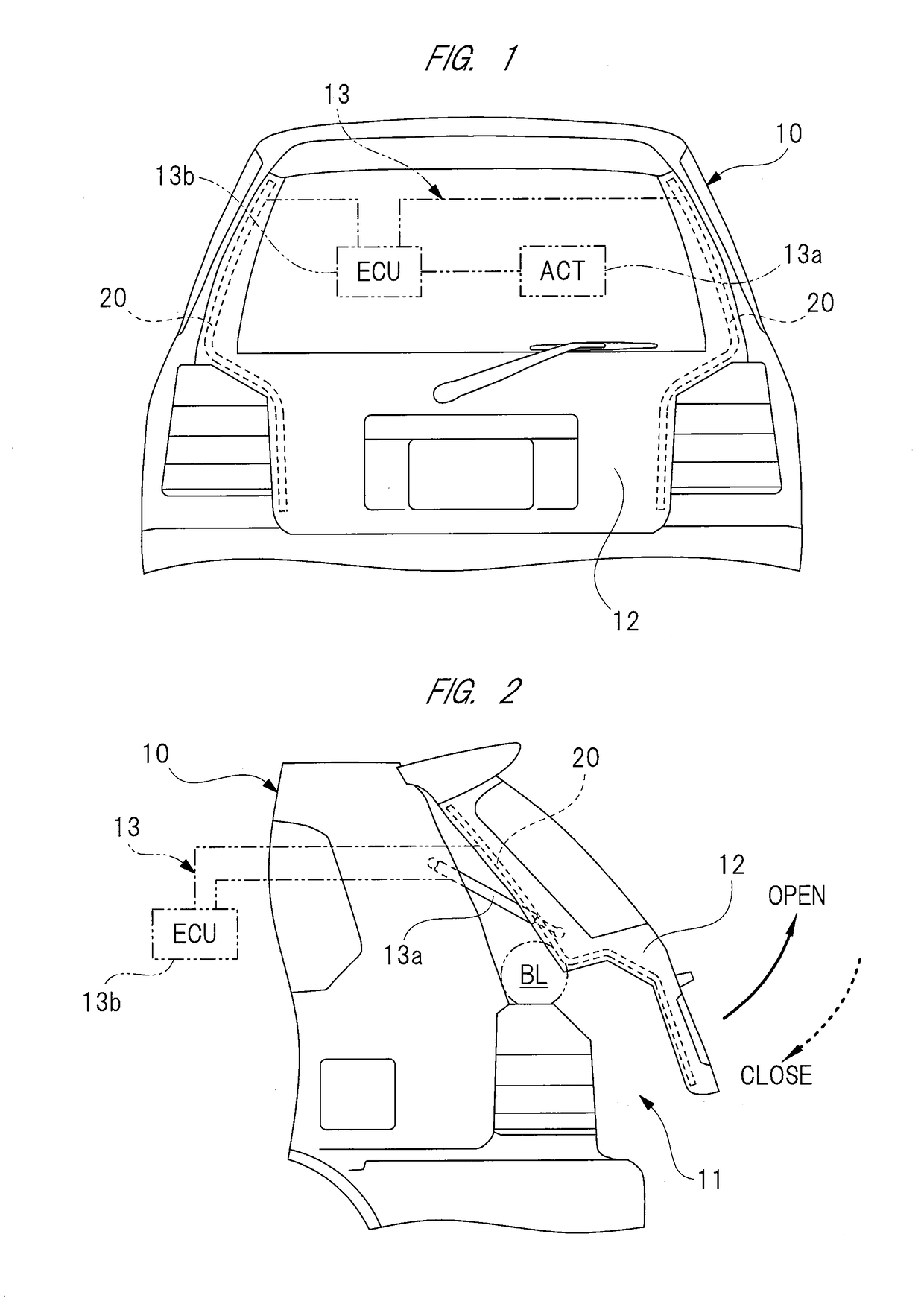
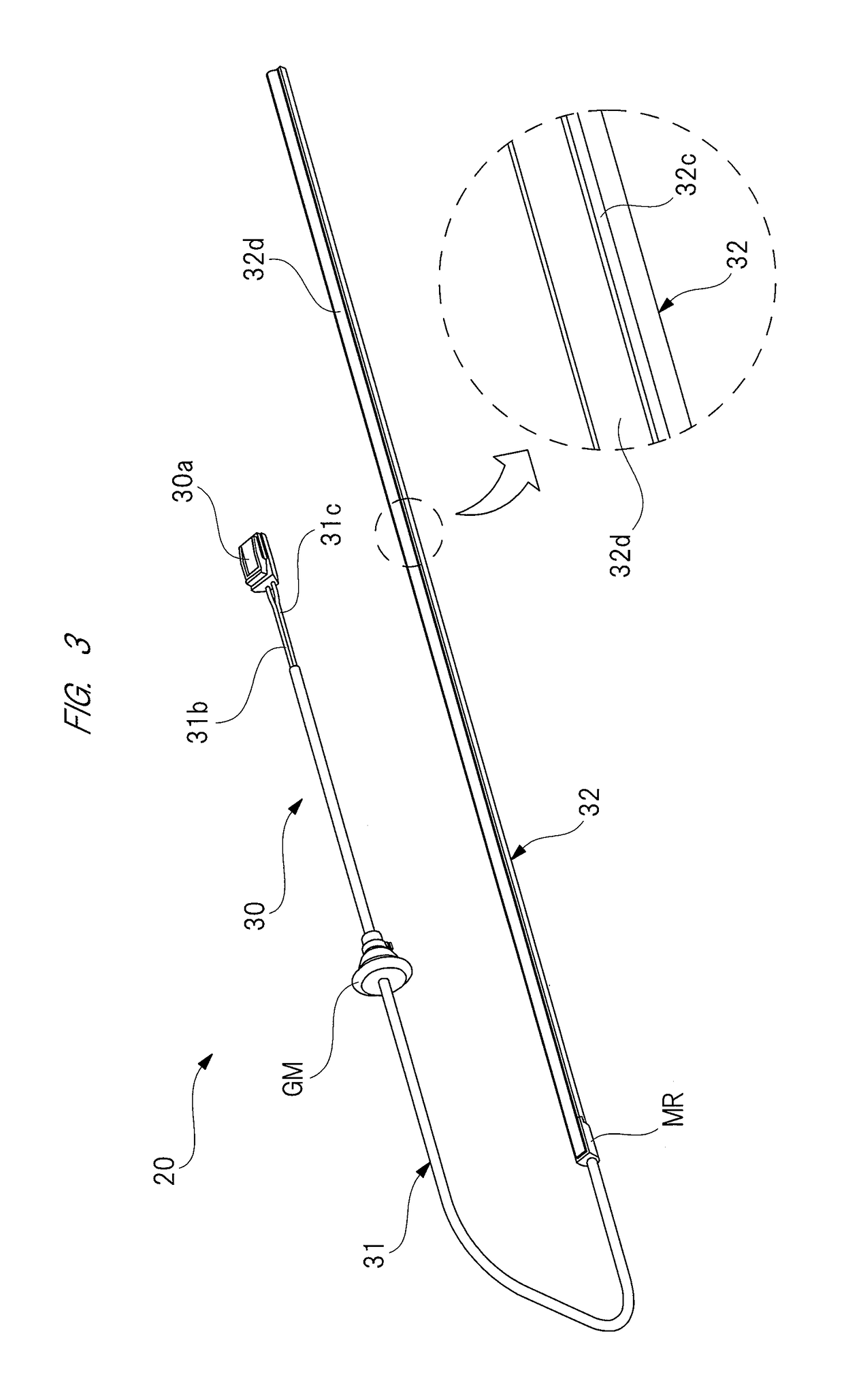
[0027]FIG. 1 is a front view of a tail gate including touch sensor units; FIG. 2 is a side view of a rear side of a vehicle in FIG. 1, from a lateral side of the vehicle; FIG. 3 is a perspective view showing a base end side of a sensor body; FIG. 4 is a perspective view showing a distal end side of the sensor body; FIG. 5 is a sectional view taken along line A-A of FIG. 4; FIG. 6 is a perspective view showing a fixing structure of the sensor body for a bracket body; FIG. 7 is a perspective view showing the touch sensor unit in FIG. 6, from the rear side; FIG. 8 is a view seen from an arrow B in FIG. 6; FIG. 9 is a view for explaining a case in which a load is applied to the sensor body from an oblique direction; FIG. 10 is a view for explaining a case in which a load is applied to the sensor body from a vertical direction; and FIG. 11 is a graph for explaining ...


PUM


Abstract

In a touch sensor unit, a bracket body is provided with a first protruding portion which is disposed on a vehicle interior side of a base portion, a gap portion is provided between the first protruding portion and the base portion, the height from the bracket body to the distal end of the first protruding portion is smaller than the height from the bracket body to the sensor portion. Therefore, when the sensor portion and the base portion are elastically deformed by contact with a blockage, the elastically deformed sensor portion and base portion enter the gap portion, thereby preventing the sensor portion and the base portion from being pressed against the corner portion of the bracket without increasing the rigidity of the sensor portion and the base portion.

Description

CROSS-REFERENCE TO RELATED APPLICATION[0001]The present application claims priority from Japanese Patent Application No. 2016-109015 filed on May 31, 2016, the content of which is hereby incorporated by reference into this application.TECHNICAL FIELD OF THE INVENTION[0002]The present invention relates to a touch sensor unit which is used for detection of contact with a blockage.BACKGROUND OF THE INVENTION[0003]Conventionally, an automatic opening and closing apparatus provided for vehicle such as automotive vehicle has: an opening and closing element which opens and closes an opening portion; an electric motor which drives the opening and closing element; and an operation switch which turns on or off the electric motor. When an operator operates the operation switch, the electric motor is driven so as to open or close the opening and closing element, and the automatic opening and closing apparatus drives the opening and closing element on the basis of not only operation of the opera...

Claims


Application Information

Patent Timeline
IPC IPC(8): E05F15/75G01D5/165
CPCE05F15/75E05Y2900/532G01D5/165E05Y2400/654E05Y2600/526E05Y2900/546E05F15/44G01D11/245
Inventor IINO, AKIHIROOKADA, MITSUHIROONODERA, KENTA
Owner MITSUBA CORP
Why Eureka
Try Eureka