Valve for liquids

Inactive Publication Date: 2010-08-19
SHIE YU MACHINE PARTS IND
View PDF25 Cites 2 Cited by
  • Summary
  • Abstract
  • Description
  • Claims
  • Application Information

AI Technical Summary

Benefits of technology

[0007]The object of this invention is to offer a valve structurally strengthened to be used in a diaphragm valve, a true union valve, a swing-type diaphragm valve, a check valve or a butterfly valve for fluids. With at least one metal ring integrally wrapped in an annular connecting circumference of a main body and at least one metal ring integrally wrapped in an annular connecting circumference of an upper lid or a connector, the valve can serve a long period of time and be used to a wide application after having the main body combined with the upper lid or the connector.
[0008]The main characteristics of the invention are a main body and an upper lid or a connector. The main body is provided with a flow passage, an annular connecting circumfe

Problems solved by technology

However, as the arc-like metal sheets 24 are independently installed on the upper lid 2, they can't be integrally formed together with the upper lid 2 firmly, forming a weak section that is possible to be damaged to pose leakage of a fl

Method used


Image

  • Valve for liquids
  • Valve for liquids
  • Valve for liquids

Examples


Example

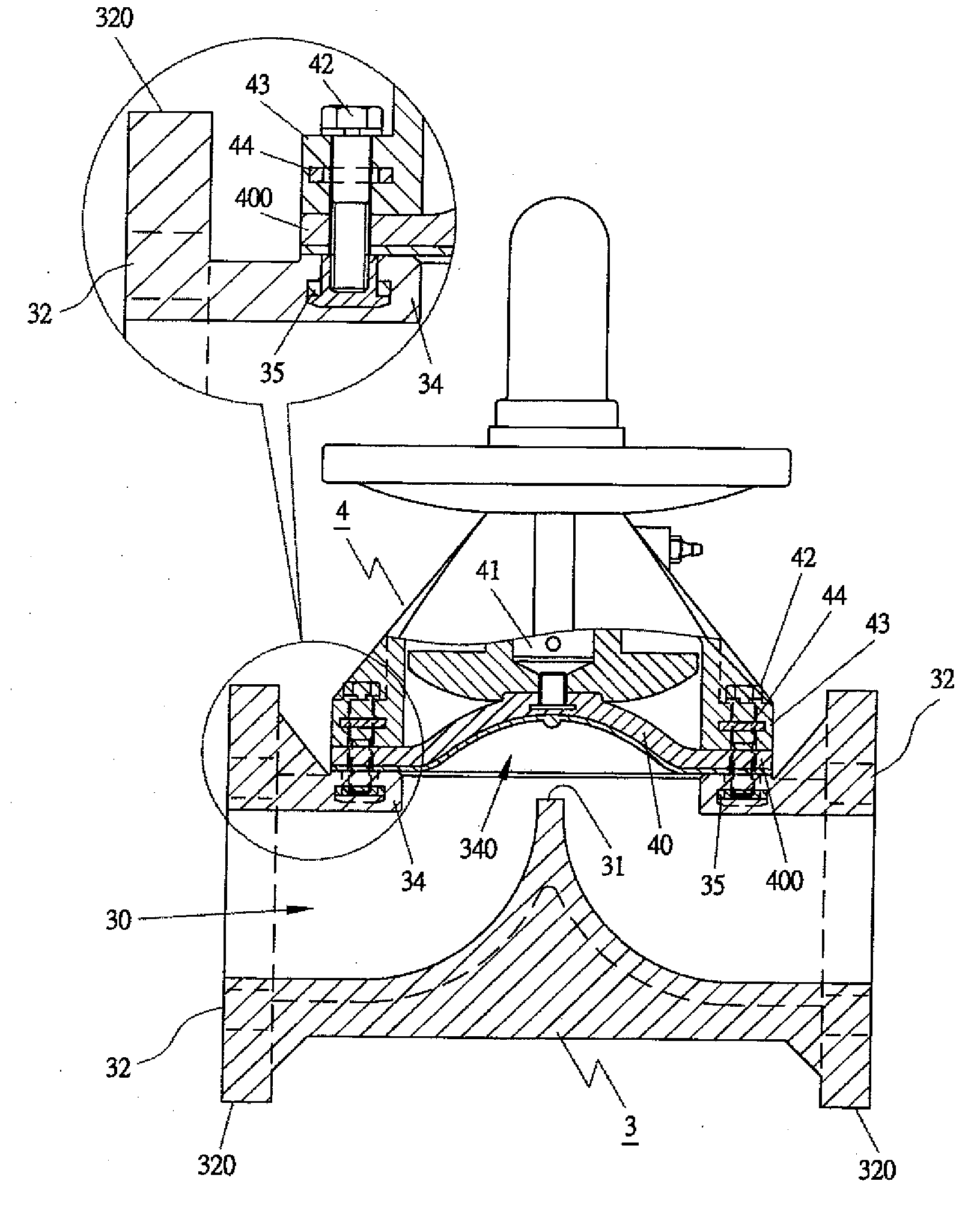
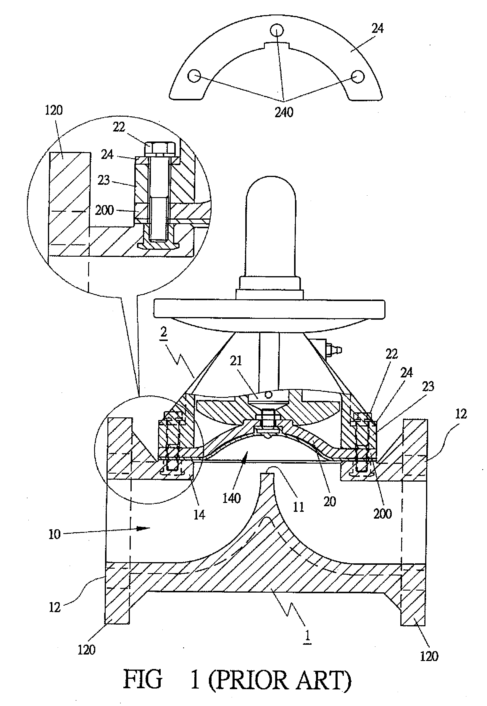
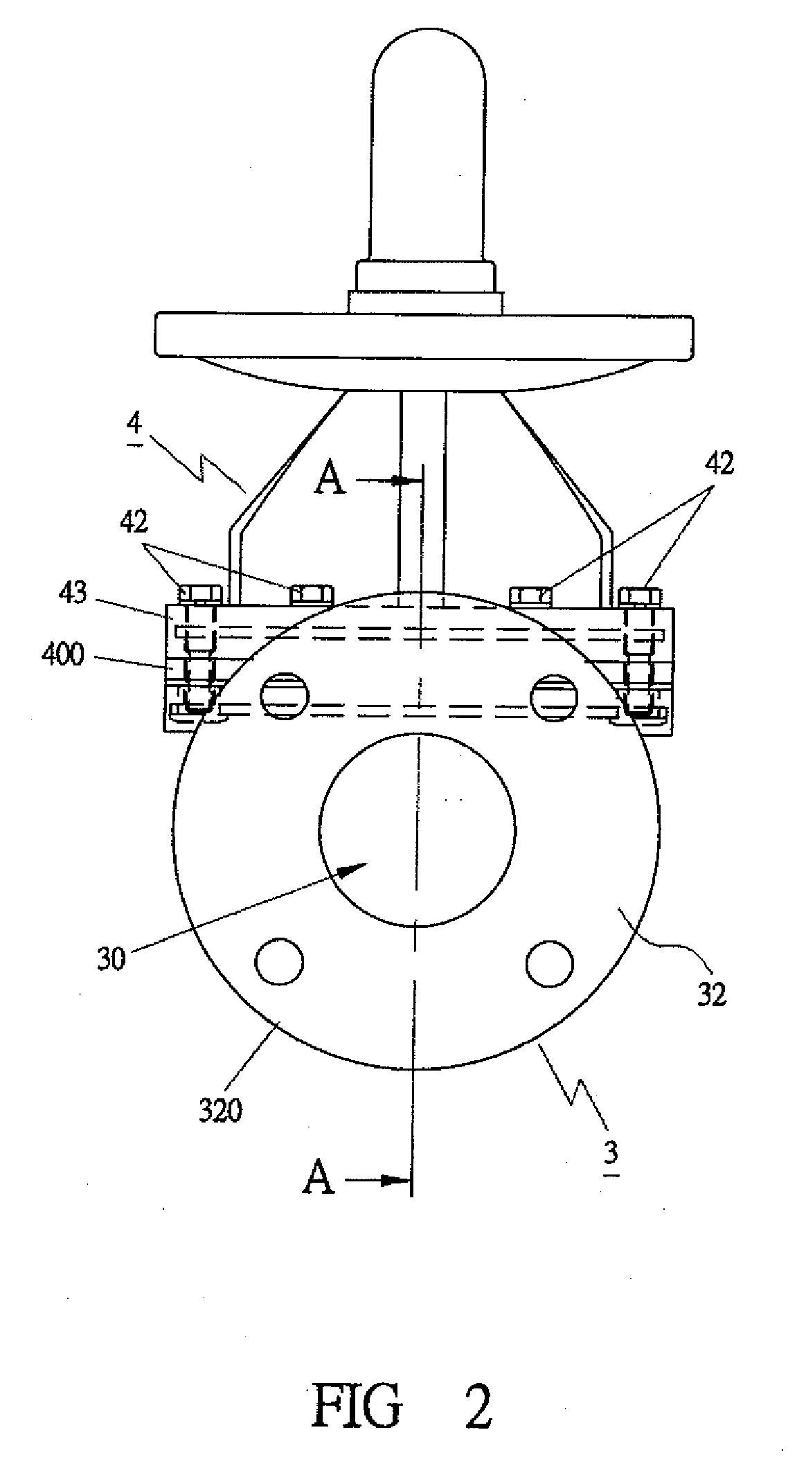
[0022]A valve for liquids in the present invention can be used in various applications, such as a diaphragm valve as shown in FIGS. 2, 3 and 6, a true union diaphragm valve as shown in FIGS. 7 and 8, a swing-type diaphragm valve as shown in FIG. 9, a check valve as shown in FIG. 10, and a butterfly diaphragm valve as shown in FIGS. 11 and 12. The valve of all embodiments in the present invention includes a main body 3 and an upper lid 4.

[0023]The main body 3 is provided with a flow passage 30 employed to collaborate with a valve sheet 40 as shown in FIGS. 3, 6, 7 and 9, with a ball valve 40A as shown in FIG. 10, or with a door valve 40B as shown in FIG. 12, so as to keep the flow passage 30 opened or closed to enable a fluid to pass through thereof or not. As shown in FIGS. 3, 6 and 7, the main body 3 is further provided with an annular connecting portion 32 formed at two sides respectively, which can be integrally reinforced with at least a metal ring 33 wrapped in an outer annular...


PUM


Abstract

A valve for liquids includes a main body and an upper lid or a connector. The main body is provided with a flow passage, an annular connecting circumference, an opening surrounded by the annular connecting circumference, and at least a metal ring integrally wrapped in the annular connecting circumference. The upper lid or the connector is provided with an annular connecting circumference having at least one metal ring integrally wrapped in it. Therefore, after having the main body combined with the upper lid or the connector, the valve can withstand comparatively large fluid pressure so as to prolong service life and be used to a wider application.

Description

BACKGROUND OF THE INVENTION[0001]1. Field of the Invention[0002]This invention relates to a valve for fluids, particularly to one able to be applied to diverse applications. With at least a metal ring integrally wrapped in an annular connecting circumference of a main body and an upper lid or a connector, the valve can withstand large fluid pressure so as to prolong service life and be used to a wide application after having the main body combined with the upper lid or the connector.[0003]2. Description of the Prior Art[0004]Commonly, as shown in FIG. 1, a conventional diaphragm valve includes a main body 1 and an upper lid 2. The main body 1 is provided with a flow passage 10 integrally formed in the interior, a projection 11 located at the middle of the flow passage 10 for co-working with the upper lid to open or close the valve to enable a fluid to pass through or not. Respectively formed at two sides of the main body 1 is an annular connecting portion 12, which is provided with ...

Claims


Application Information

Patent Timeline
IPC IPC(8): F16K13/00
CPCF16K27/12F16K7/126
Inventor TSAI, CHI-LUNG
Owner SHIE YU MACHINE PARTS IND
Why Eureka
Try Eureka