Gimbaled flexure for spherical flex joints

Active Publication Date: 2018-07-19
UNISON INDUSTRIES
View PDF0 Cites 4 Cited by
  • Summary
  • Abstract
  • Description
  • Claims
  • Application Information

AI Technical Summary

Benefits of technology

The patent text describes a duct assembly for gas turbine engines that includes a first duct and a second duct connected by a flexible joint assembly. The flexible joint assembly includes a bellows with convolutions and a gimbal joint assembly with a support ring and flexure hinges. The joint assembly also includes a gimbal ring assembly that is connected to the support rings. These configurations provide flexibility and allow for the reduction of stress and strain on the duct assembly during operation. The technical effect of this invention is to improve the performance and reliability of gas turbine engines.

Problems solved by technology

Current systems use ball-joints or axial joints in the duct to meet requirements for flexibility, which compromise system dynamic performance and increase the weight of the system.

Method used


Image

  • Gimbaled flexure for spherical flex joints
  • Gimbaled flexure for spherical flex joints
  • Gimbaled flexure for spherical flex joints

Examples


Embodiment Construction

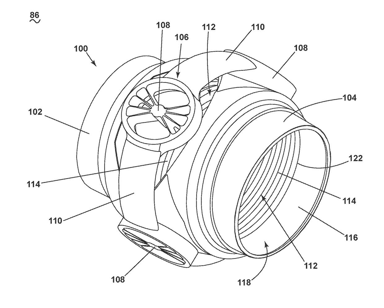
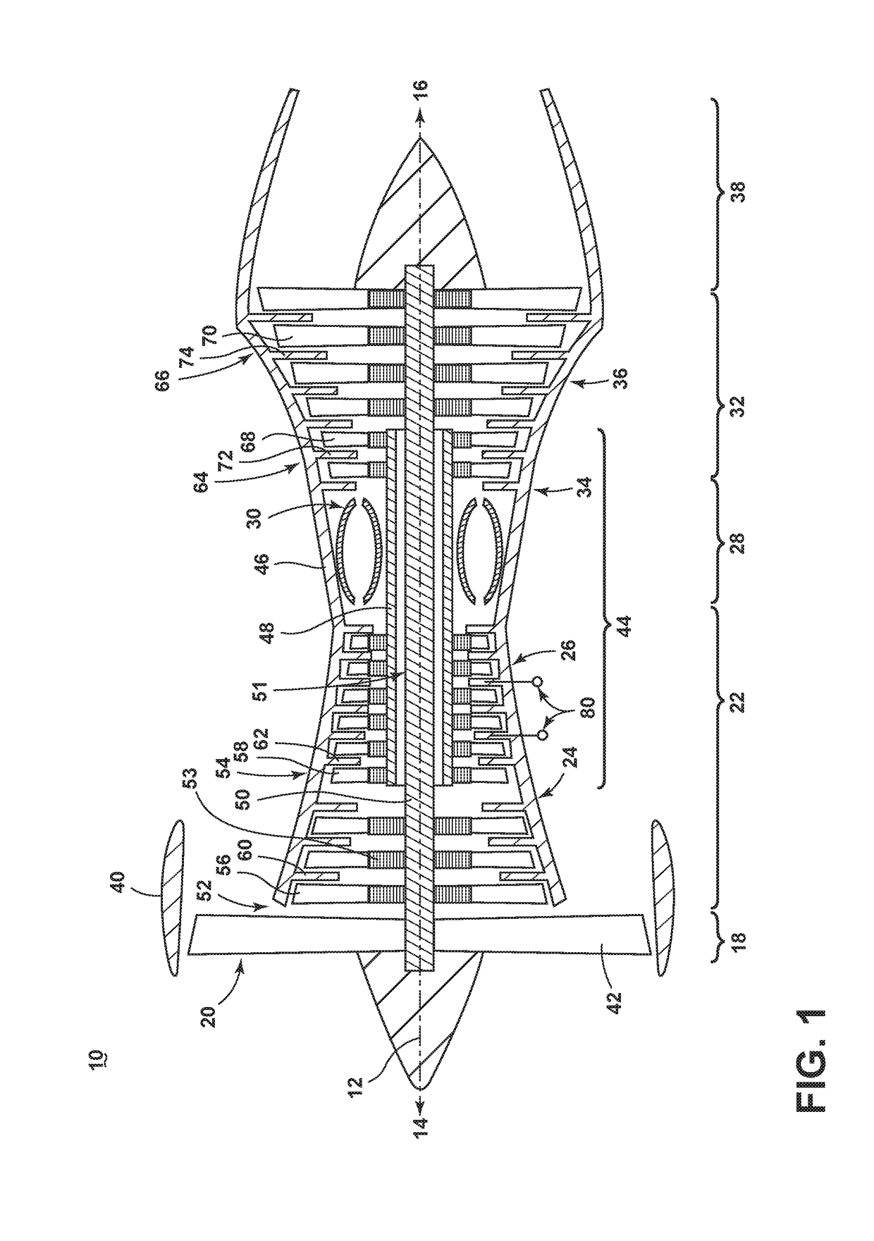
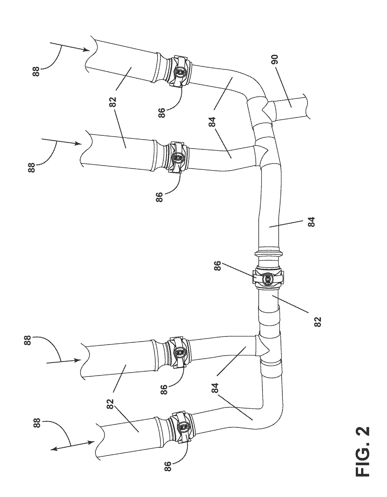
[0021]The aspects of present disclosure are directed to providing a flex joint. Such a flex joint can be utilized for improved rotational compliance for reduced reaction loading into the case of turbine engines during assembly, operation, and thermal growth of high temperature bleed-air ducting systems. Thus, for purposes of illustration, the present invention will be described with respect to a gas turbine engine. Gas turbine engines have been used for land and nautical locomotion and power generation, but are most commonly used for aeronautical applications such as for airplanes, including helicopters. In airplanes, gas turbine engines are used for propulsion of the aircraft. It will be understood, however, that the invention is not so limited and can have general applicability in non-aircraft applications, such as other mobile applications and non-mobile industrial, commercial, and residential applications. Additionally, the described embodiments will have equal applicability to ...


PUM


Abstract

A flexible joint assembly for a joint between a first duct and a second duct for providing a flow of fluid, such as bleed air in an aviation implementation. The flexible joint includes a bellows supported by a mounting assembly having a first support and a second support, each surrounding a portion of the bellows. A set of flexures provided on a joint ring of the joint assemblies can operably couple the first support and the second support.

Description

BACKGROUND OF THE INVENTION[0001]Turbine engines, and particularly gas or combustion turbine engines, are rotary engines that extract energy from a flow of combusted gases passing through the engine in a series of compressor stages, which include pairs of rotating blades and stationary vanes, through a combustor, and then onto a multitude of turbine stages, also including multiple pairs of rotating blades and stationary vanes.[0002]Duct assemblies are provided about the turbine engine and provide conduits for the flow of various operating fluids to and from the turbine engine. One of the operating fluids is bleed air. In the compressor stages, bleed air is produced and taken from the compressor via feeder ducts. Bleed air from the compressor stages in the gas turbine engine can be utilized in various ways. For example, bleed air can provide pressure for the aircraft cabin, keep critical parts of the aircraft ice-free, or can be used to start remaining engines. Configuration of the f...

Claims


Application Information

Patent Timeline
IPC IPC(8): F16L27/02F04D27/00
CPCF04D27/009F16L27/02F16L27/0857F02C7/00
Inventor TAJIRI, GORDONKENWORTHY, MICHAEL THOMASJONNALAGADDA, DATTU GVBURDETTE, JASON L.
Owner UNISON INDUSTRIES
Why Eureka
Try Eureka