Drawer Panel Adjusting Device

a technology for adjusting devices and drawers, which is applied in the direction of drawers, furniture parts, domestic applications, etc., can solve the problem of reducing the overall quality of furnitur

Inactive Publication Date: 2018-08-16
GUANGDONG XINGPENG IND CO LTD
View PDF0 Cites 1 Cited by
  • Summary
  • Abstract
  • Description
  • Claims
  • Application Information

AI Technical Summary

Benefits of technology

[0006]It is therefore the primary objective of this invention to provide a drawer panel adjusting device which permits the front panel of each drawer of the furniture to move upward, downward, rightward, and leftward relative to other boards to precisely align the front panels of all drawers of the furniture.
[0009]The drawer panel adjusting device according to the present invention provides a simple structure that can easily be operated to adjust the position of a front panel of a drawer, such that the front panel can move upward, downward, leftward, or rightward relative to a bottom board and a side board of the drawer to align with the front panels of other drawers, improving the overall sense of quality of the furniture.
[0010]In an example, the first movable member includes a main board. The first adjusting hole is defined in a side of the main board. The assembling groove is defined in the other side of the main board. This structure is simple and is easy to manufacture and assemble, reducing the manufacturing costs and increasing the assembling convenience.
[0011]In an example, the second movable member includes an engaging groove. The first movable member further includes an extension board and a clamping board. The extension board is connected to the main board. The clamping board is fixed to the extension board. An elastic element and an engaging unit are clamped between the clamping board and the extension board. The elastic element abuts the engaging unit. The engaging unit is pivotable to engage with the engaging groove of the second movable member. This structure permits the second movable member to be rapidly and securely assembled and positioned to the first movable member, increasing the convenience and efficiency of assembly.
[0012]In an example, the engaging unit includes a push plate and an insertion plate. The push plate includes a push end insertable into the assembling groove. The insertion plate includes an abutting end and an insertion end opposite to the abutting end. An end of the elastic element abuts the abutting end. The push plate is pivotable to disengage the push end from the assembling groove. The insertion end of the insertion plate is inserted into the engaging groove. This structure is simple and is easy to manufacture and assemble, reducing the manufacturing costs and increasing the assembling convenience.
[0013]In an example, the push plate includes a first pivotal hole and a through-hole. The insertion plate further includes a second pivotal hole. A pin extends through the first pivotal hole of the push plate and the second pivotal hole of the insertion plate into a longitudinal limiting hole of the extension board. The through-hole of the push plate remains aligned with a horizontal limiting hole of the extension board. This structure is simple and is easy to manufacture and assemble, reducing the manufacturing costs and increasing the assembling convenience.

Problems solved by technology

However, even if the furniture with drawers is made with good material and impeccable color, the overall sense of quality of the furniture is decreased if the panels of the drawers cannot align precisely.

Method used


Image

  • Drawer Panel Adjusting Device
  • Drawer Panel Adjusting Device
  • Drawer Panel Adjusting Device

Examples


Embodiment Construction

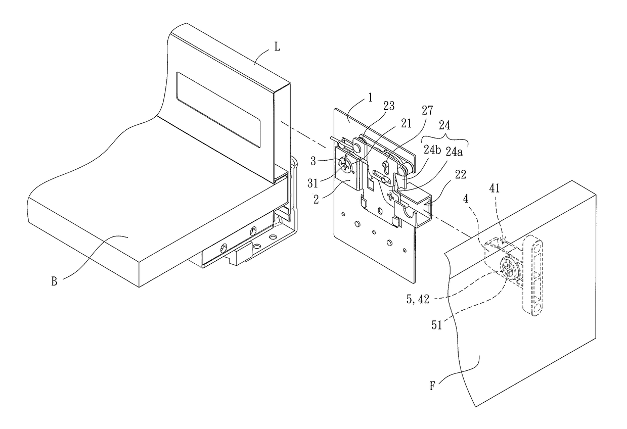
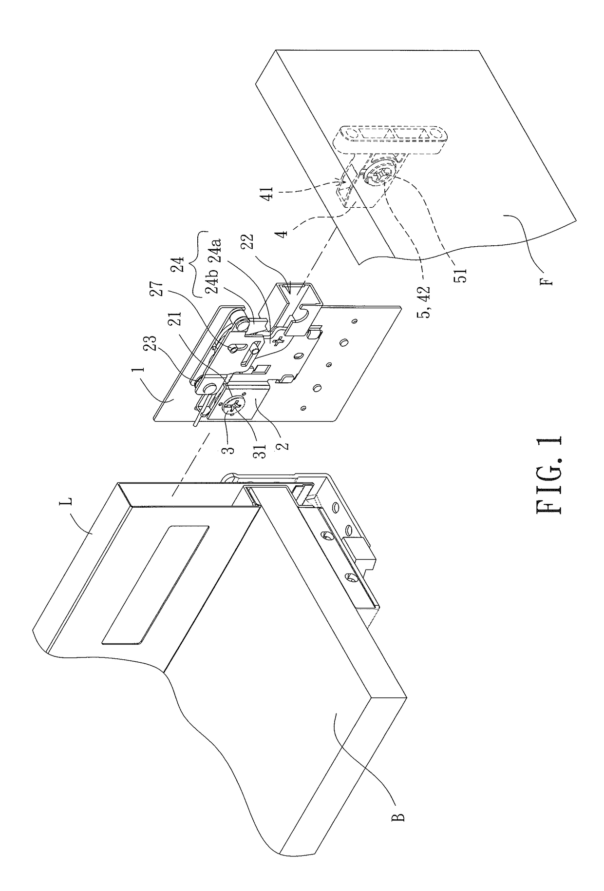
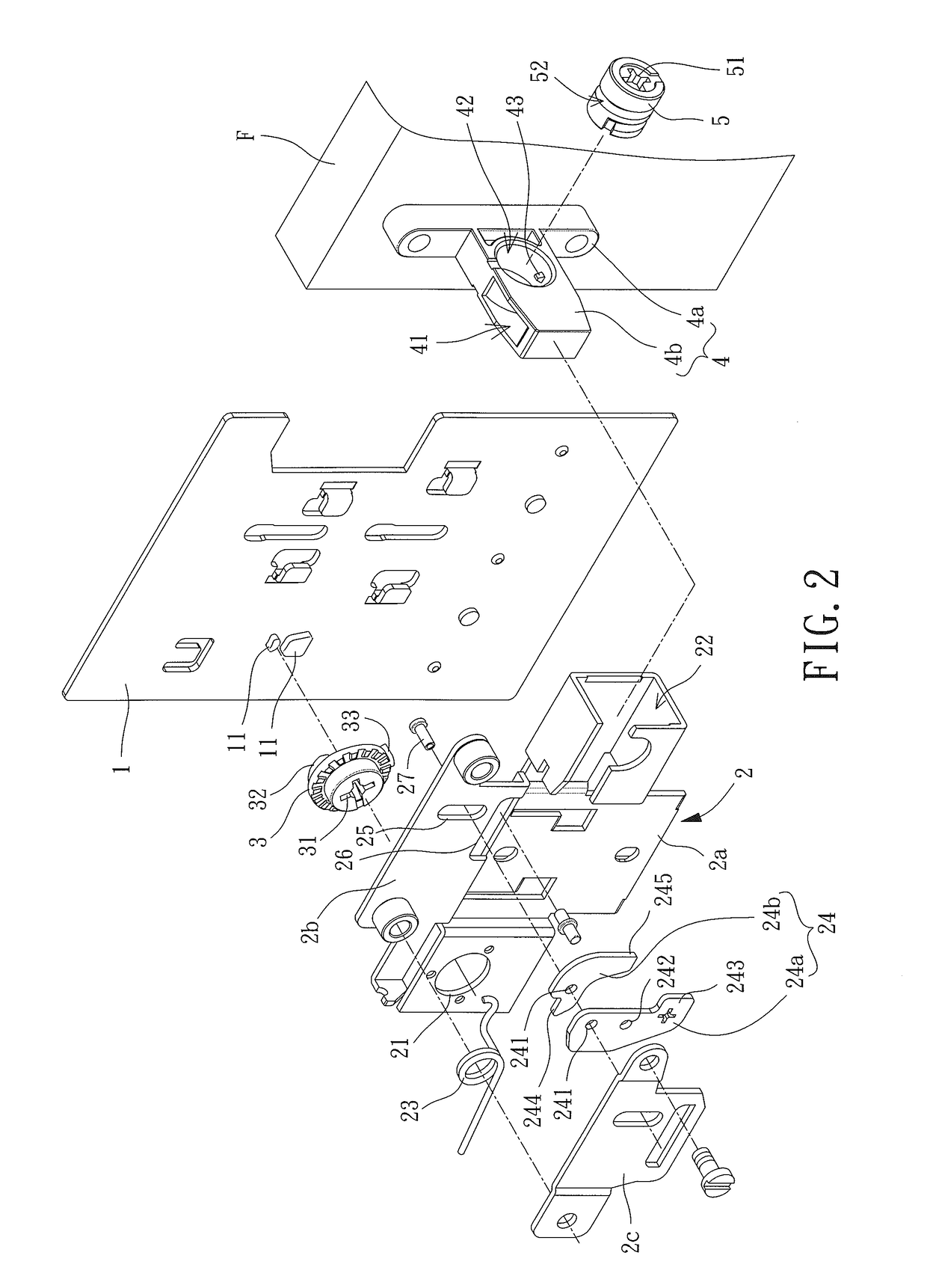
[0022]With reference to FIGS. 1 and 2, a drawer panel adjusting device of an embodiment according to the present invention includes a fixed member 1, a first movable member 2, a first adjusting member 3, a second movable member 4, and a second adjusting member 5. The first adjusting member 3 is mounted between the fixed member 1 and the first movable member 2. When the first adjusting member 3 is rotated, the first movable member 2 moves upward or downward relative to the fixed member 1. A front panel F of a drawer is fixed to the second movable member 4. The second movable member 4 is assembled to the first movable member 2. The second adjusting member 5 is mounted in the second movable member 4. When the second adjusting member 5 is rotated, the second movable member 4 moves leftward or rightward relative to the first movable member 2.

[0023]Specifically, the fixed member 1 extends into a side board L of the drawer and is fixed to a bottom board B of the drawer. The fixed member 1 ...


PUM


Abstract

A drawer panel adjusting device includes a fixed member, a first movable member, a first adjusting member, a second movable member, and a second adjusting member. The first adjusting member is located between the fixed member and the first movable member. A spiral block on the first adjusting member extends through a gap between two limiting blocks on the fixed member. The second movable member is mounted in an assembling groove of the first movable member. The second movable member includes a second adjusting hole and a guiding block located in the second adjusting hole. The second adjusting member includes an outer periphery having a spiral guiding groove. The second adjusting member extends through the second adjusting hole and is restrained in the assembling groove. The guiding block is engaged in the spiral guiding groove.

Description

CROSS REFERENCE TO RELATED APPLICATIONS[0001]The application claims the benefit of China application serial No. 201710083049.1, filed on Feb. 16, 2017, and the entire contents of which are incorporated herein by reference.BACKGROUND OF THE INVENTION1. Field of the Invention[0002]The present invention generally relates to a part for a drawer and, more particularly, to a drawer panel adjusting device mounted to a front end of a drawer.2. Description of the Related Art[0003]In general, every drawer includes a bottom board, a front panel, a rear board, and two side boards. The front panel and the rear board are mounted to front and rear ends of the bottom board, and the two side boards are mounted to the left and right sides of the bottom board, together defining a space having an open top end for receiving articles.[0004]With the improvement of the quality of life in the past few years, people are no longer merely satisfied with the utility of the furniture. The critical factor for peo...

Claims


Application Information

Patent Timeline
Patent Type & Authority Applications(United States)
IPC IPC(8): A47B88/956A47B88/90
CPCA47B88/956A47B2088/952A47B88/941A47B95/00A47B2088/951A47B2088/954
Inventor SU, SHU-PENG
Owner GUANGDONG XINGPENG IND CO LTD
Why Eureka
Try Eureka