Internal combustion engine

Active Publication Date: 2018-08-16
TOYOTA JIDOSHA KK
View PDF0 Cites 5 Cited by
  • Summary
  • Abstract
  • Description
  • Claims
  • Application Information

AI Technical Summary

Benefits of technology

[0015]According to the aspect of the disclosure, the second communication hole on the exhaust side is inclined so as to be directed further in the D direction as it is positioned toward the outside from the inside of the sub-chamber. The direction of the inclination of the second communication hole coincides with the direction of a tumble flow in the main combustion chamber. Therefore, the purge gas that is discharged into the main combustion chamber through the second communication hole acts so as to further strengthen the tumble flow. This action contributes to improvement in the combustibility in the main combustion chamber.
[0016]According to the aspect of the disclosure, the first communication hole on the intake side narrows toward the inside from the outside of the sub-chamber. Therefore, the intake flow easily enters the sub-chamber through the first communication hole, and the purge gas in the sub-chamber is difficult to flow out from the first communication hole to the outside of the sub-chamber. Therefore, the purge performance in the sub-chamber is further improved.
[0017]According to the aspect of the disclosure, the second communication hole on the exhaust side narrows toward the outside from the inside of the sub-chamber. Therefore, the purge gas is the sub-chamber is easily discharged from the second communication hole to the outside, and the gas in the main combustion chamber is difficult to enter the sub-chamber through the second communication hole. Therefore, the purge performance in the sub-chamber is further improved. Further, a jet at the time of combu

Problems solved by technology

That is, when a lot of residual gas from the previous cycle remains in the sub-chamber, ignitability and combustibility in the sub-chamber deteriorate.
Therefore, the intake flow easily enters the sub-chamber through the first communication hole, and the purge gas in the sub-chamber is difficult to flow out from the first communication hole to the outside of the sub-chamber.
Therefore, the purge gas is the sub-chamber is

Method used


Image

  • Internal combustion engine
  • Internal combustion engine
  • Internal combustion engine

Examples


Example

[0037]Embodiments of the disclosure will be described with reference to the accompanying drawings.

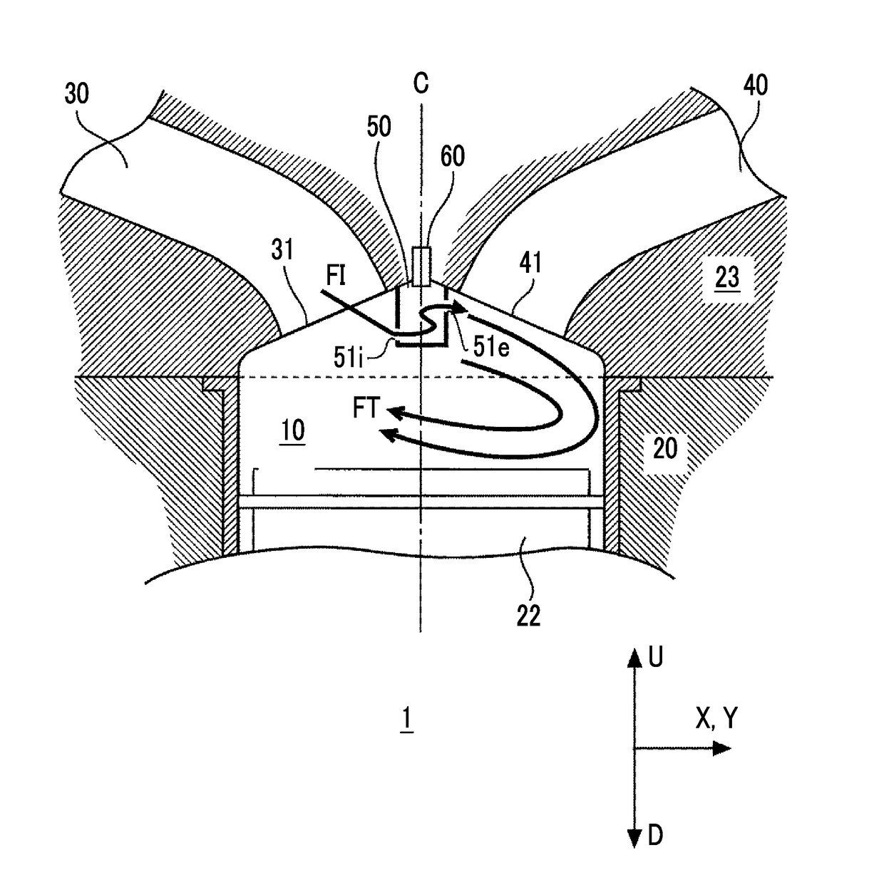
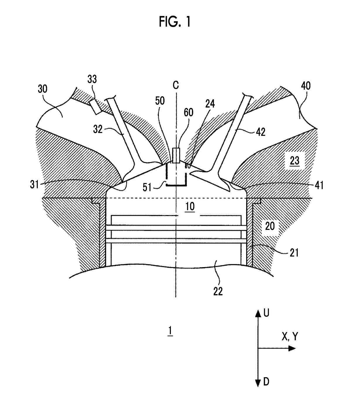
[0038]FIG. 1 is a sectional view schematically showing a configuration example of an internal combustion engine 1 according to a first embodiment of the disclosure. The internal combustion engine 1 is configured to mainly include a main combustion chamber 10, an intake port 30, an exhaust port 40, a sub-chamber 50, and a spark plug 60.

[0039]The main combustion chamber 10 is a space surrounded by a cylinder block 20, a piston 22, and a cylinder head 23. More specifically, the cylinder block 20 is provided with a cylindrical cylinder liner 21 (a cylinder bore) forming the side wall of the main combustion chamber 10. In the drawings, the central axis of the cylindrical cylinder liner 21 is represented by a symbol “C”. The piston 22 is disposed so as to be able to reciprocate along an axial direction of the cylinder liner 21. The upper surface of the piston 22 forms the bottom surface of th...


PUM


Abstract

An internal combustion engine includes: a main combustion chamber; an intake port connected to the main combustion chamber; an exhaust port connected to the main combustion chamber; a sub-chamber; and a spark plug in the sub-chamber. The sub-chamber is provided between the intake opening portion and the exhaust opening portion and connected to the main combustion chamber through a plurality of communication holes. The communication holes include a first communication hole provided on the intake opening portion side, and a second communication hole provided on the exhaust opening portion side. The first communication hole is closer to a piston than the second communication hole is. The first communication hole is inclined to be closer to the piston as the first communication hole is positioned toward the inside from the outside of the sub-chamber.

Description

CROSS-REFERENCE TO RELATED APPLICATIONS[0001]This application claims priority to Japanese Patent Application No. 2017-024075 filed on Feb. 13, 2017, which is incorporated herein by reference in its entirety inducing the specification, drawings and abstract.BACKGROUND1. Technical Field[0002]The disclosure relates to an internal combustion engine in which spark ignition is performed in a sub-chamber provided in a main combustion chamber.2. Description of Related Art[0003]Japanese Unexamined Patent Application Publication No. 8-284665 (JP 8-284665 A) discloses an internal combustion engine having a main combustion chamber and a sub-chamber provided in the main combustion chamber. The sub-chamber is connected to the main combustion chamber through a communication hole. In a compression process, a part of an air-fuel mixture in the main combustion chamber enters the sub-chamber through the communication hole. A spark plug is provided in the sub-chamber and combustion is started by perfor...

Claims


Application Information

Patent Timeline
IPC IPC(8): F02B19/18F02B19/12F02B19/08
CPCF02B19/18F02B19/12F02B19/08H01T13/54Y02T10/12F02B23/08
Inventor MORI, SACHIO
Owner TOYOTA JIDOSHA KK
Why Eureka
Try Eureka