Electronic apparatus

a technology of electronic equipment and mounting devices, which is applied in the direction of portable computer details, electric equipment casings/cabinets/drawers, instruments, etc., can solve the problems of difficult detachment of mounting devices b>1/b> itself from the vehicle, and the inability to detach the second casing, so as to improve the convenience of the user, improve the strength of locking, and improve the effect of security

Active Publication Date: 2018-08-16
PANASONIC INTELLECTUAL PROPERTY MANAGEMENT CO LTD
View PDF12 Cites 4 Cited by
  • Summary
  • Abstract
  • Description
  • Claims
  • Application Information

AI Technical Summary

Benefits of technology

[0086]Further, in electronic device 100 of the present disclosure, when electronic device 100 is locked to mounting device 1, it is no longer necessary for the user to perform lock operation on each of first unit 101 and second unit 102. Therefore, convenience of the user improves.
[0088]Electronic device 100 of the present exemplary embodiment includes first unit 101 having the input part and second unit 102 having the display, and first unit 101 and second unit 102 are detachably coupled. First unit 101 includes socket 130 capable of housing a predetermined side of second unit 102. Locked holes 130a, 120a (insertion holes), into which lock projection 23b (a security member) of lock member 23 can be inserted, are provided on one of the right and left sides of socket 130 and second unit 102.
[0089]Interlocking lock mechanism 200 is provided on another of the right and left sides of socket 130 and second unit 102. Interlocking lock mechanism 200 locks second unit 102 to socket 130 when lock projection 23b (the security member) of lock member 23 is inserted into locked holes 130a, 120a (the insertion holes).
[0090]With this configuration, in electronic device 100 of the present exemplary embodiment, when lock projection 23b (the security ...

Problems solved by technology

Meanwhile, it is considered that a lock structure identical to a lock structure of the first casing is also applied to the second ca...

Method used


Image

  • Electronic apparatus
  • Electronic apparatus
  • Electronic apparatus

Examples


first exemplary embodiment

[0029]Hereinafter, a first exemplary embodiment is described with reference to the drawings.

[1. Configuration]

[1-1. Configuration of Electronic Device]

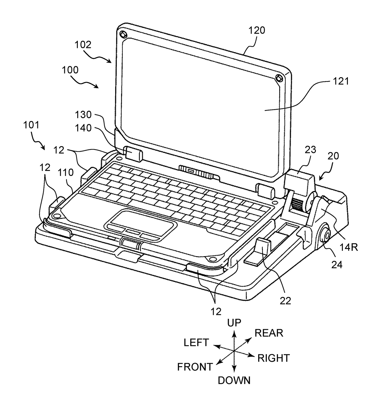
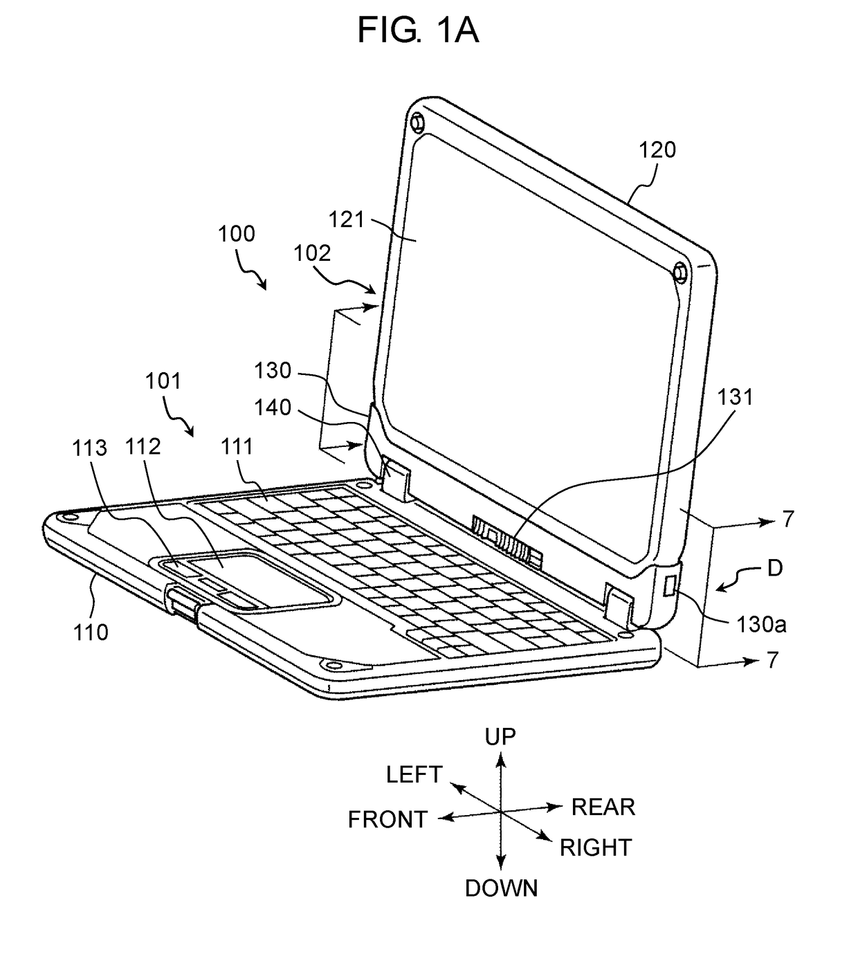
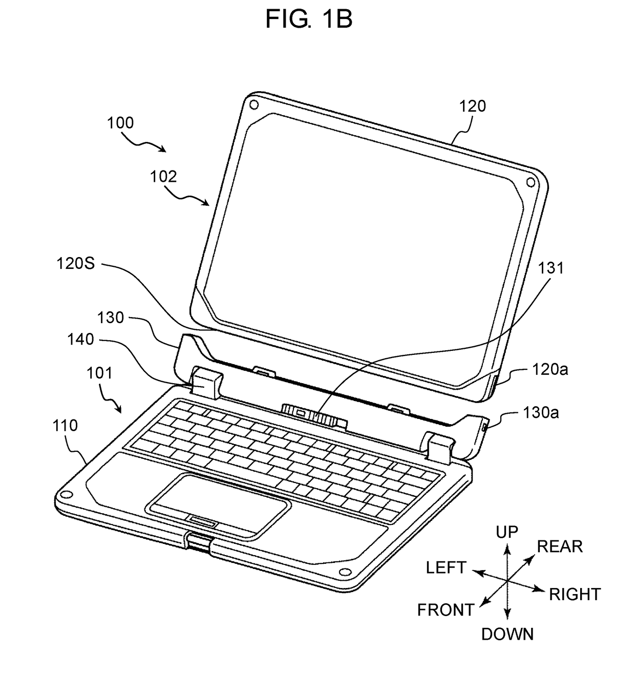
[0030]FIG. 1A is a perspective view of an electronic device according to the first exemplary embodiment of the present disclosure. FIG. 1B is a perspective view (a perspective view seen from a right side) showing a state in which the electronic device according to the first exemplary embodiment of the present disclosure is separated into a first unit and a second unit. FIG. 1C is a perspective view (a perspective view seen from a left side) showing the state in which the electronic device according to the first exemplary embodiment of the present disclosure is separated into the first unit and the second unit.

[0031]As shown in FIG. 1A, directions are defined herein to explain a configuration of the electronic device. It should be noted that the definitions are for convenience of explanation of the configuration of the electronic devic...


PUM


Abstract

An electronic device includes a first unit having an input part and a second unit having a display. The first unit and the second unit are detachably coupled. The first unit includes a socket capable of housing a predetermined side of the second unit. Locked holes, into which a lock projection of a lock member can be inserted, are provided on one of right and left sides of the socket and the second unit. An interlocking lock mechanism is provided on another of the right and left sides of the socket and the second unit. The interlocking lock mechanism locks the second unit to the socket when the lock projection of the lock member is inserted into the locked holes.

Description

BACKGROUND1. Technical Field[0001]The present disclosure relates to an electronic device in which a first casing and a second casing are detachable.2. Description of the Related Art[0002]PTL 1 discloses a docking station (a mounting device) capable of mounting a notebook type computer (an electronic device). Normally, the notebook type computer has a first casing having a keyboard and a central processing unit and a second casing having a display. The first casing and the second casing are coupled such that they are relatively rotatable around a first rotating axial center. In the docking station in PTL 1, a mounting part, on which the first casing is mounted, is provided on an upper surface of a case (a casing). The mounting part includes a hook member (a lock member) lockable to a locked hole. The locked hole is provided on a bottom surface of the first casing of the notebook type computer. By operating an operating member, the lock member can be moved between a lock state in whic...

Claims


Application Information

Patent Timeline
IPC IPC(8): G06F21/88G06F1/16H05K5/02
CPCG06F21/88G06F1/1616G06F1/1654H05K5/0221G06F1/1633
Inventor MORI, TAKESHISHINDO, KENICHIKATSUYAMA, YUSUKE
Owner PANASONIC INTELLECTUAL PROPERTY MANAGEMENT CO LTD
Why Eureka
Try Eureka