
Methods for making a bag from a film material exhibiting textile properties

Inactive Publication Date: 2018-08-23
RASMUSSEN OLE BENDT
View PDF0 Cites 0 Cited by
  • Summary
  • Abstract
  • Description
  • Claims
  • Application Information

AI Technical Summary

Benefits of technology

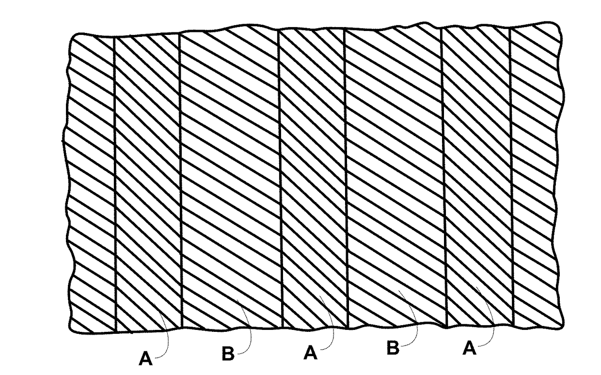
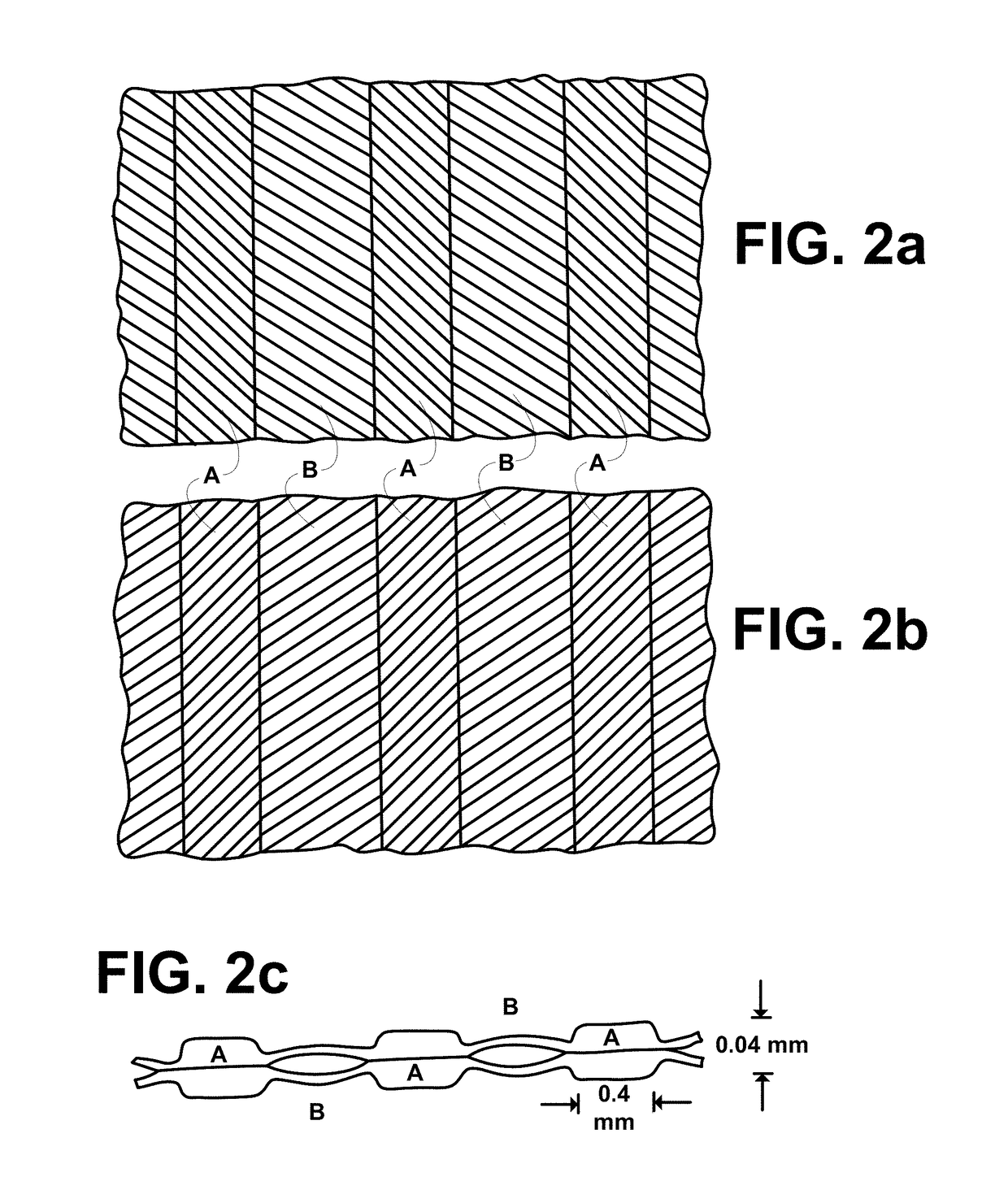
The present invention describes a film or assembly of films made of thermoplastic polymer material that have a unique arrangement of parallel band-shaped regions and linearly extending webs that connect the regions. The orientation of the regions forms angles with the direction in which the film extends, while the orientation of the webs creates angles with the direction in which the film extends. The method of production involves stretching the film or assembly using a pair of mutually intermeshing rollers, which can create distinct division between the linearly extending webs and band-shaped regions. The technical effect of this invention is the creation of a film or assembly with a unique arrangement of parallel band-shaped regions and linearly extending webs that have superior properties, such as high strength and flexibility, and can be used in various applications.

Problems solved by technology

During the last 40-50 years there have been presented a number of proposals and a few industrial processes for manufacture of film materials formed of thermoplastic polymer material exhibiting textile properties, but due to complications in the manufacturing process and / or relatively high machine costs, these technologies have in general not been competitive with non-woven technologies based on spun filaments.
In particular this has been a difficulty for materials with low weight per area.

Method used


Image

  • Methods for making a bag from a film material exhibiting textile properties
  • Methods for making a bag from a film material exhibiting textile properties
  • Methods for making a bag from a film material exhibiting textile properties

Examples


example 1

[0107]A tubular film of average gauge 18.6 micron (measured as 17.9 g / m2) is coextruded having the following composition:[0108]Middle layer, 65% of total: all HMWHDPE except for additives and white masterbatch.[0109]Outer surface layer, 15% of total: 70% LLDPE of m.f.i.=1.0+30% metalocene PE melting between 50-60° C.[0110]Inner surface layer, 100% LLDPE

[0111]The blow up ratio is 2.7:1 and the gap of the circular die orifice is 1.0 mm. This means that the tubular film, while getting its thickness reduced by a factor of about 50, gets a strong predominantly longitudinal melt orientation.

[0112]This tubular film is helically cut to form a web with 45° orientation. Two such webs are assembled on a 40° C. warm roller with their directions of orientation crossing each other. In line herewith the assembly is transversely stretched between the grooved rollers shown in FIG. 3. The roller temperature is maintained at 20° C. by means of circulating water. The width of each flat crest is 0.4 mm ...

example 2

[0118]There is used the same extruded film, the same helical cutting under 45°, and the same crosslamination and transverse stretching I laminating process as in Example 1, but before helical cutting the lay-flat tubular film is m.d. stretched in sequential manner between grooved rollers which have teeth extending parallel to the axis. The crests of these teeth are semicircular with diameter 1.9 mm, and the pitch of the grooves on each roller is 5.0 mm. By the applied inlet and outlet tension in the film and the intermeshing between the rollers the average stretching ratio is adapted to be 1.4:1. The stretching takes place on the rounded teeth on one of the grooved rollers and between the teeth, while film on the teeth of the other roller remains unstretched.

[0119]The testing of the produced crosslaminate is recorded below.

Comparative Testing of Example 1 and Example 2 Film.

[0120]The two crosslaminates and the extruded tubular film are tensile tested and tested for puncture strength...

example 3

[0132]There is used the same extruded films as in Example 1, and the same sequential m.d. stretching as in Example 2. Helical cutting is carried out under 30° to the original m.d. The film with 30° orientation is transversely stretched / embossed, in part as a single film, and in part cross webbed with itself between sharp-edged grooved rollers. The grooved rollers and the grooved roller process deviate from what is described in Example 1 only on the following points:[0133]1) The grooves are made slightly deeper to allow a deeper intermeshing, and this is set at 1.2 mm.[0134]2) One of the two grooved rollers with sharp-edged crests has a waved surface, exactly as shown in FIG. 9a. The intermeshing by 1.2 mm refers to the top sections of the waving.[0135]3) The process is carried out at ambient temperature 25° C.

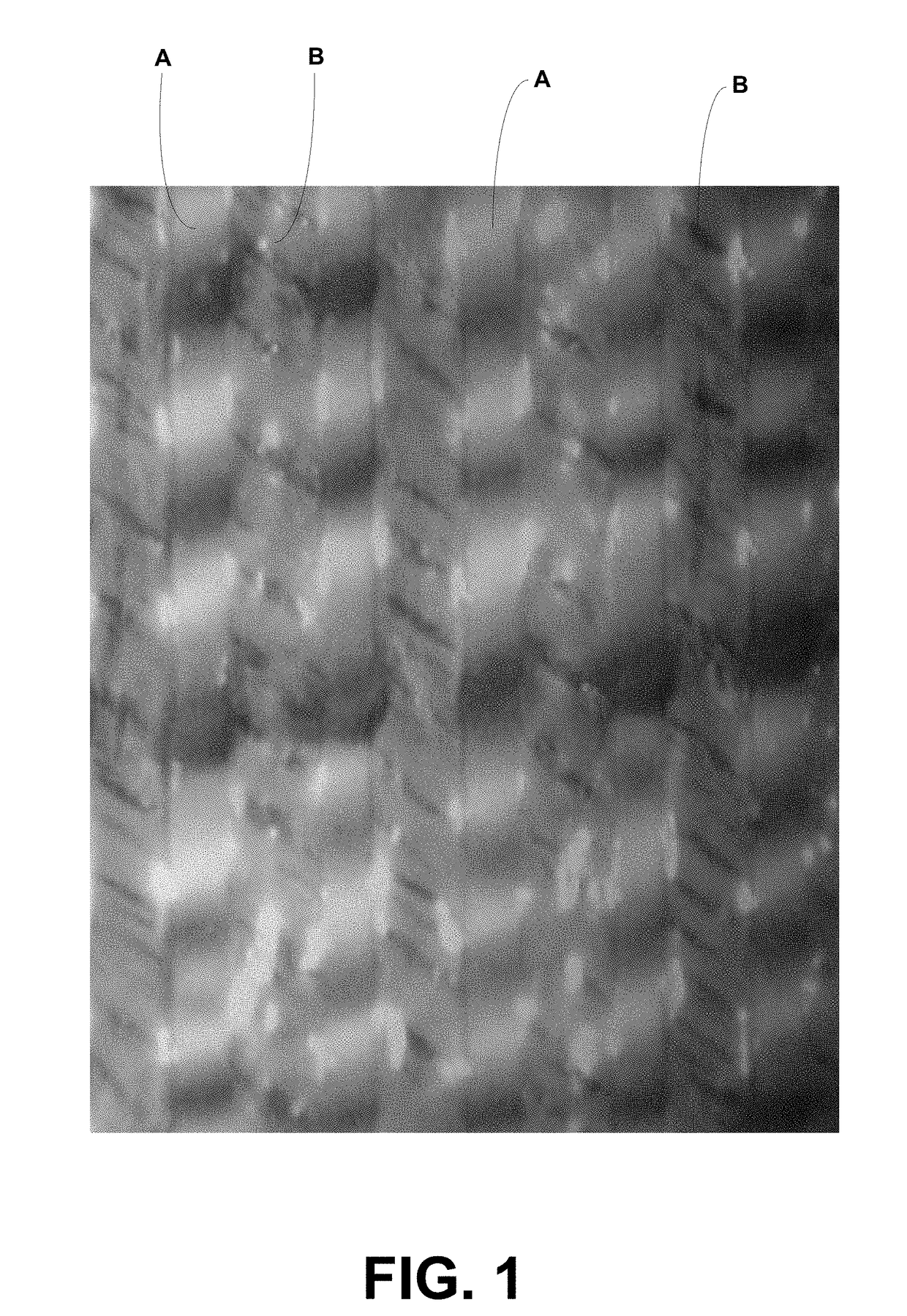
[0136]The produced single ply has gauge 9.5 g / m2, and the produced crosslaminate is 19 g / m2. A microphoto of the single ply film is shown as FIG. 12. The structure of the two p...


PUM

PropertyMeasurementUnit
Angleaaaaaaaaaa
Lengthaaaaaaaaaa
Lengthaaaaaaaaaa

Abstract

A film material formed of thermoplastic polymer material is processed so as to have linearly extending regions (A) linked together by linearly extending webs (B), regions (A) and webs (B) each being oriented, the dominant direction of orientation in regions (A) forming an angle (V) to the direction on which (A) extends and webs (B) comprising arrays of linear furrows of thinner material or splits forming angles (U) higher than (V) to the direction in which (A) extends. The method of producing the new film involves passing an orientated film through a pair of intermeshing grooved rollers to cold-stretch the film in a direction at an angle to the predominant original orientation, at least one of the grooved rollers having crests with sharp edges to form the division between regions A and webs B and to stretch the material to form webs B while stretching the material less or not at all to form regions A. Preferably at least one of the grooved rollers has crests with a waved surface shape.

Description

RELATED APPLICATIONS[0001]This application is continuation-in-part of U.S. patent application Ser. No. 14 / 741,095 filed 16 Jun. 2015 (06 / 16 / 2015) (16.06.2015), which is a continuation of U.S. patent application Ser. No. 14 / 023,120 filed 10 Sep. 2013 (09 / 10 / 2013) (10.09.2013) now U.S. Pat. No. 9,108,356 issued 18 Aug. 2015 (08 / 18 / 2015) (18.08 / 2015), which is a divisional of U.S. patent application Ser. No. 12 / 863,283 filed 16 Jul. 2010 (07 / 16 / 2010) (16.07.2010) now U.S. Pat. No. 8,557,364 issued 15 Oct. 2013 (10 / 15 / 2013) (15.10.2013), which claims priority to and the benefit of PCT / EP2009 / 050412 filed 15 Jan. 2009 (01 / 15 / 2009) (15.01.2009) claiming priority to GB0800828.6 filed 17 Jan. 2008 (01 / 17 / 2008) (17.01.2008) and GB0814308.3 filed 5 Aug. 2008 (08 / 05 / 2008) (05.08.2008).BACKGROUND OF THE INVENTION1. Field of the Invention[0002]The object of the invention appears from the title. By textile properties there is primarily meant a soft and warm handle. In particular the invention con...

Claims


Application Information

Patent Timeline
IPC IPC(8): B32B3/28B32B27/08B32B7/00B32B27/32B65F1/00B32B7/035
CPCB32B3/28B32B27/08B32B7/005B32B27/32B65F1/0006B32B2439/06B65F2250/114B32B2038/0028B32B37/0053B32B7/035
Inventor RASMUSSENRASMUSSEN, NIKOLAI WETTERGREN WETTERGREN
Owner RASMUSSEN OLE BENDT
Learn More